Using GPS on RISC OS Part 4 - Additional information
A series of articles has been published in Archive Magazine describing the design and construction of a GPS receiver and speedometer:
- In part 1 (Archive 24:2) I described a Raspberry Pi that could be carried around: instead of a mouse and monitor it had an Adafruit touchscreen that just plugged in to the HDMI and USB sockets. It had a GPS module sending position data to the mapping application (RiscOSM) by means of URI_Dispatch messages generated by the !Satnav application. It thus provided a rolling map of your location using Open Street Map data.
- Part 2 (Archive 24:3) described version 1.08 of Satnav, which could control a small text display or an OLED display and could talk to RiscOSM using Wimp messages.
- Part 3 (Archive 24:4) adds a Witty Pi for control of power consumption. Satnav is at version 1.40 and can control an ‘electronic ink’ display (Papirus).
- Part 4 (Archive 24:5, expected November 2018) adds an Adafruit power-boost board to extend battery life, an Adafruit ADS1015 ADC board to provide battery management, improved odometer function, and adds software-controlled power-switching. GPX logging, rather than Anquet AEF format, internationalizes Satnav, now at version 1.80. At each stage the hardware has become smaller.
- Some of this information is available here.
- Further information to conclude the series is given below.
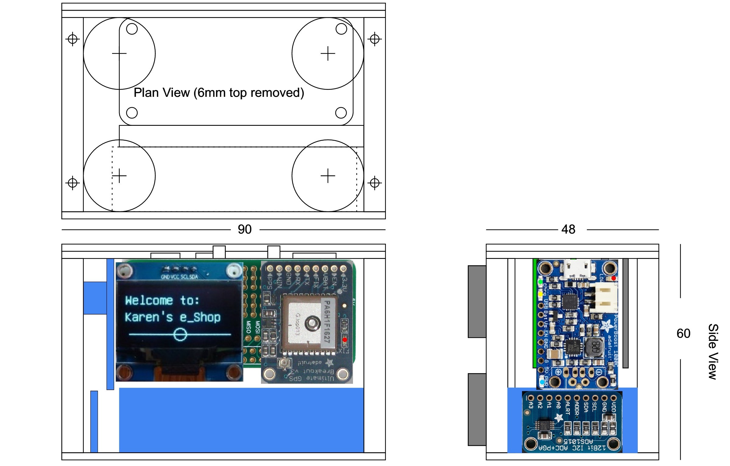
The latest version of my satellite device is the most compact. Designed to log a railway journey (or car journey) with a continuous display of speed in miles per hour, the unit will function for 17 hours from a full charge. It fits easily into a pocket and has two push buttons, one for 'ON' and one for 'OFF' and can be set to require two separate presses to turn off (so that it doesn't switch itself off in my pocket when I accidentally touch it). This web site page describes the construction of the unit in more detail than could be included in the series of articles in Archive magazine (parts 1 to 4).
Under construction
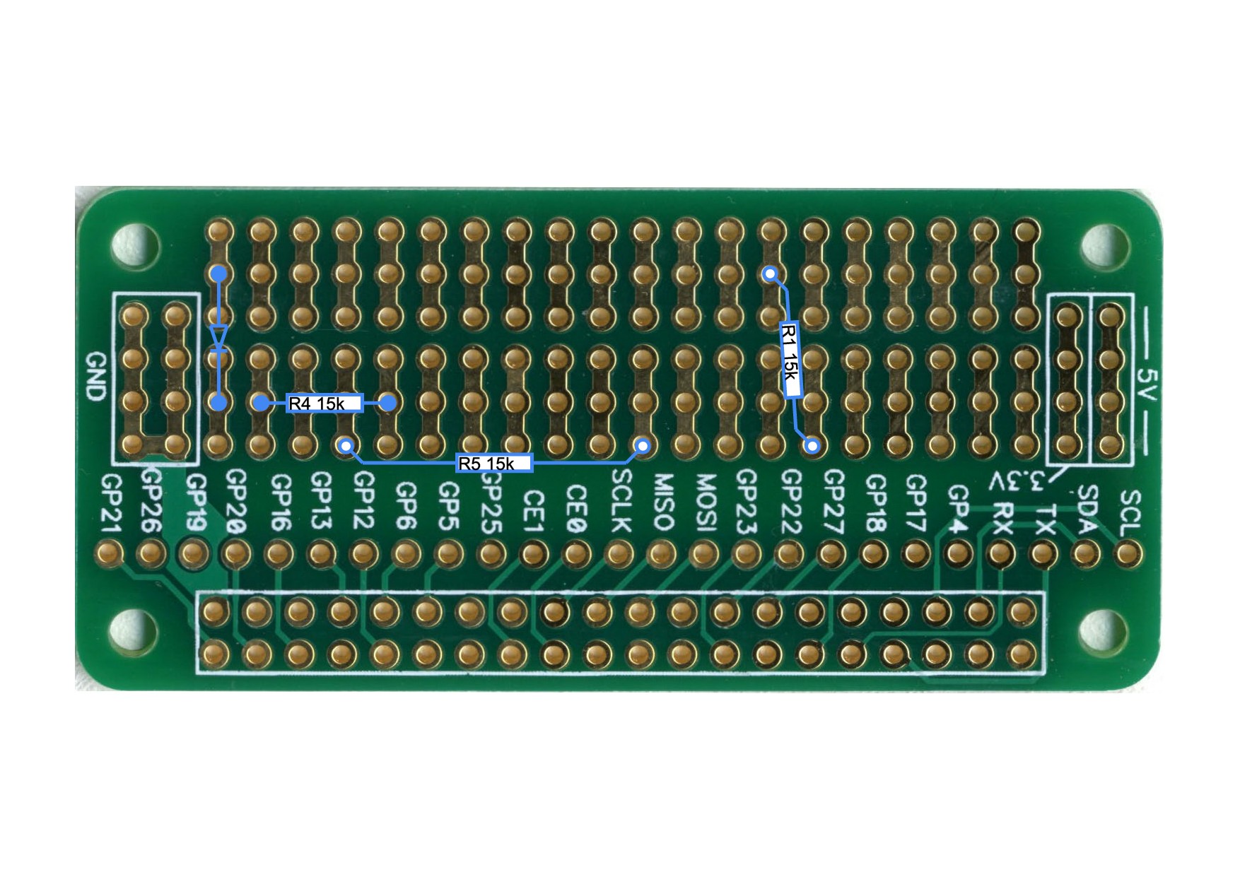
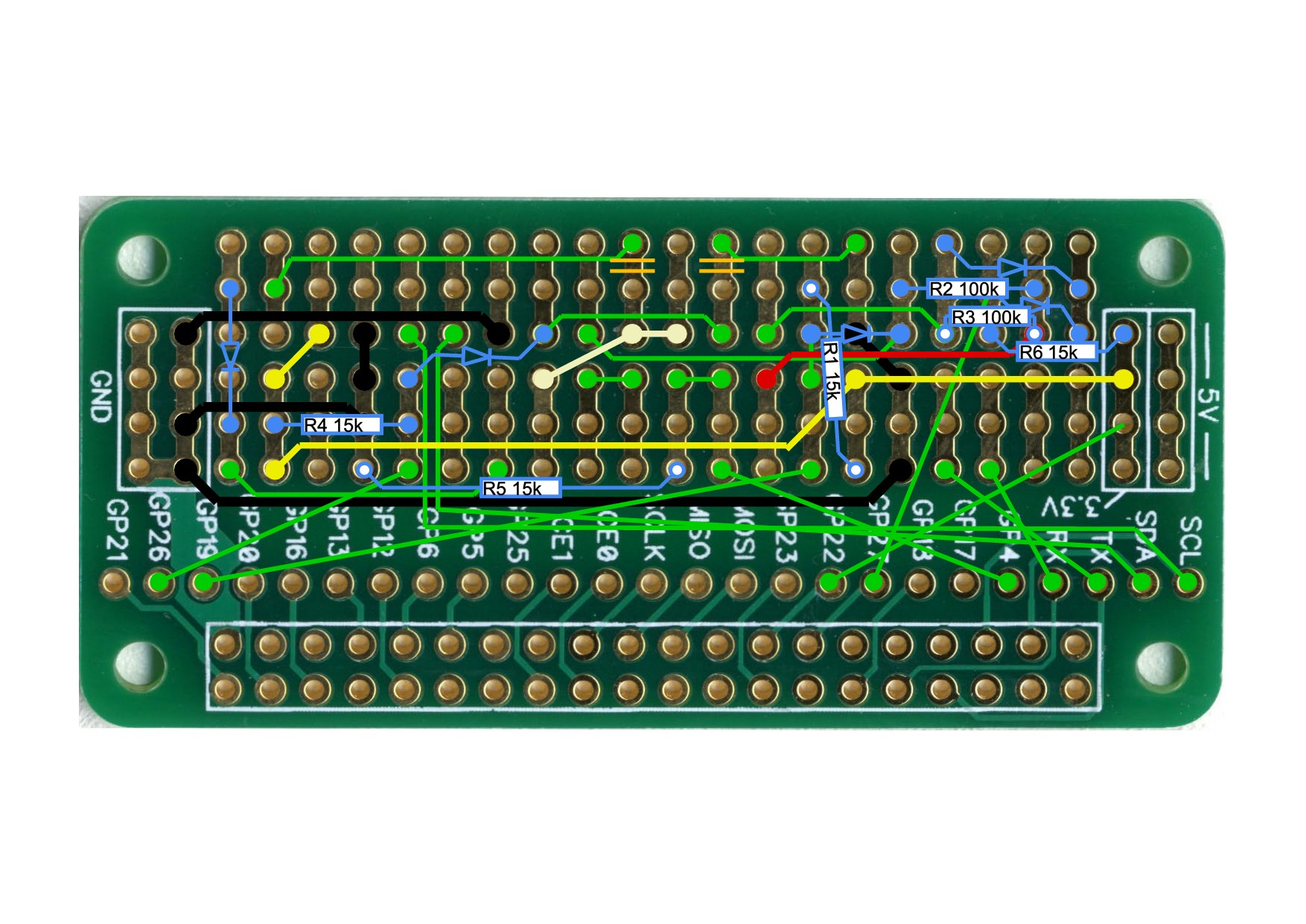
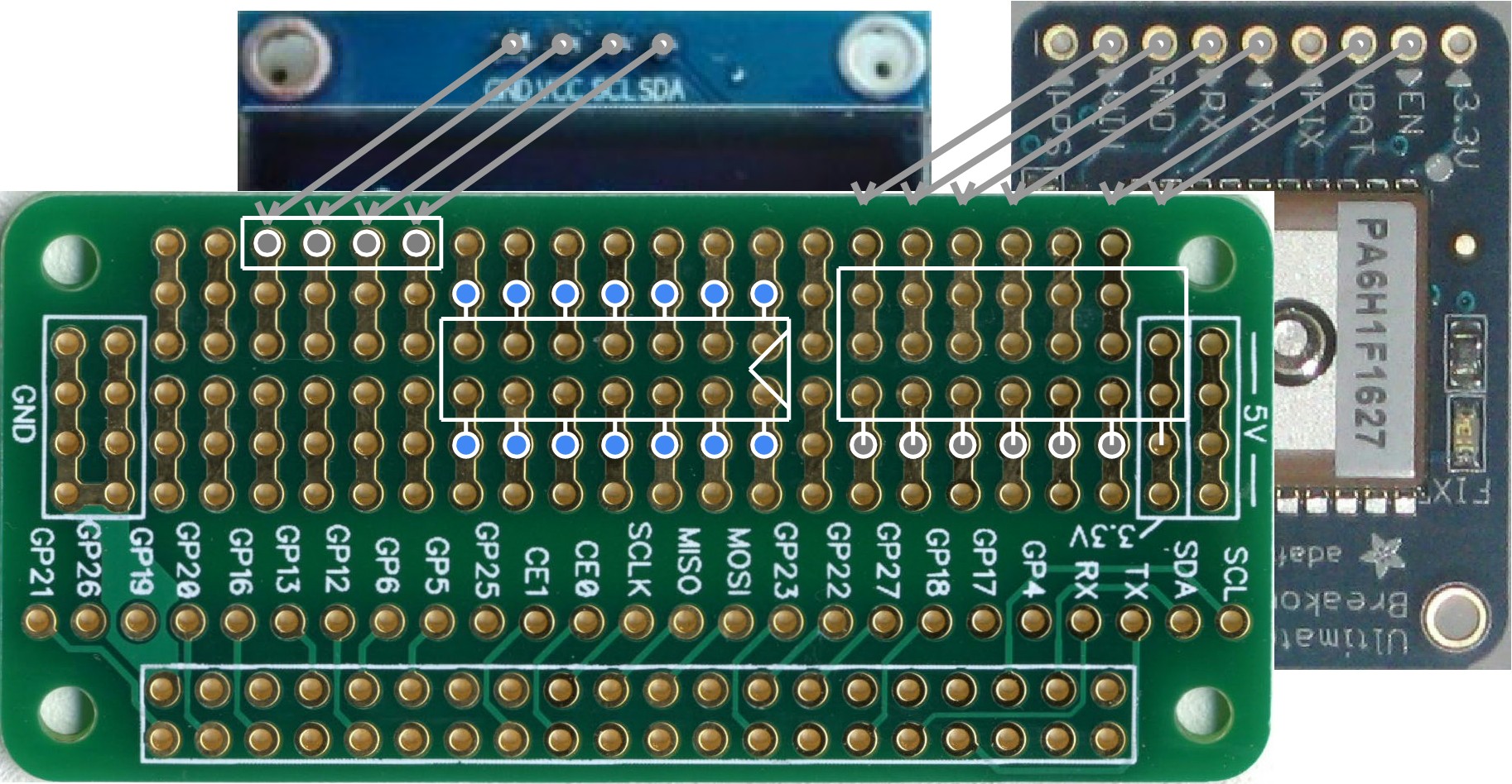
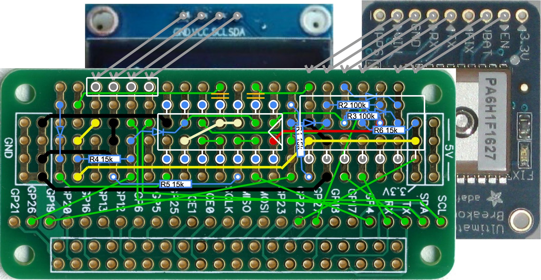
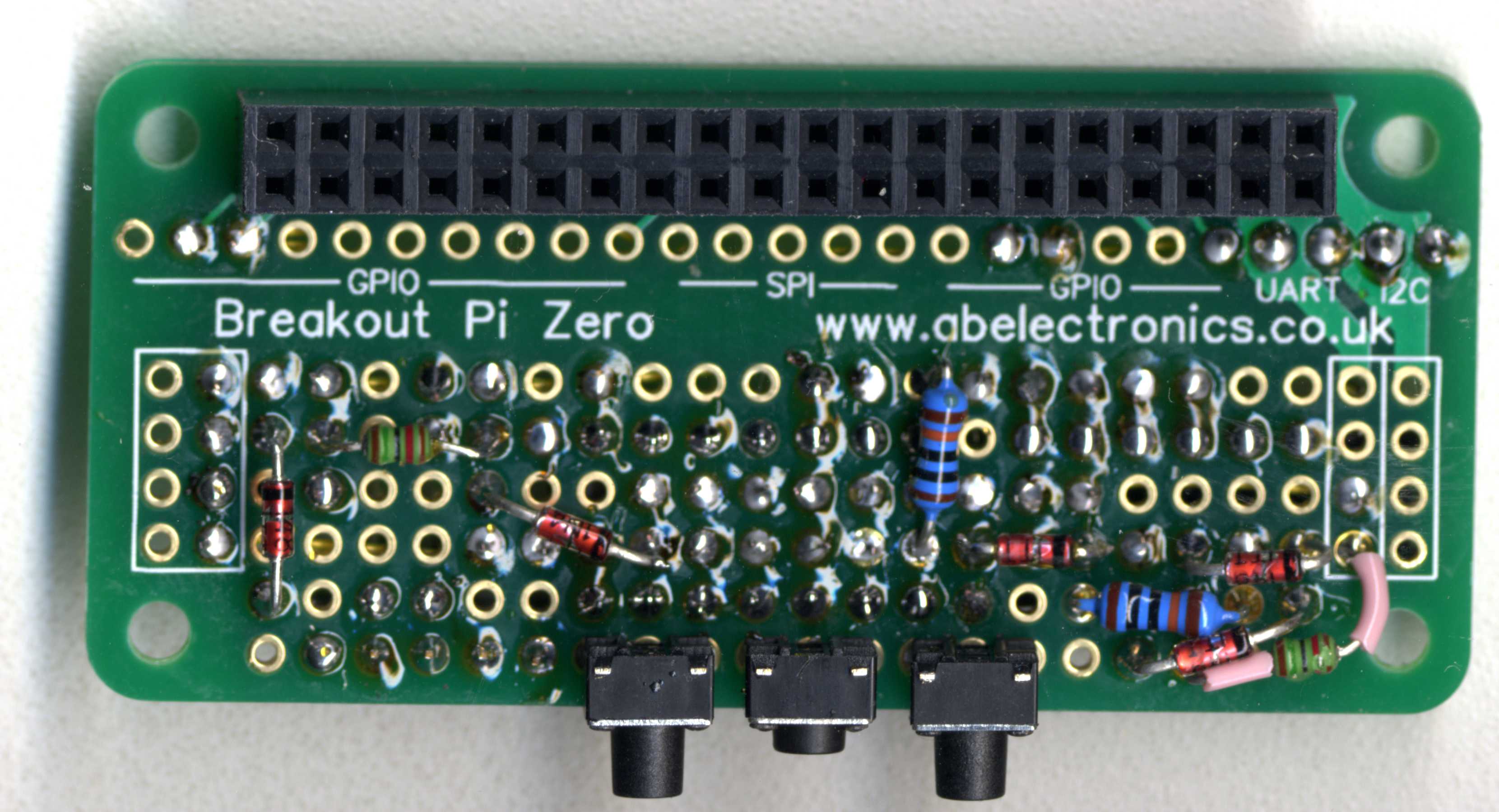
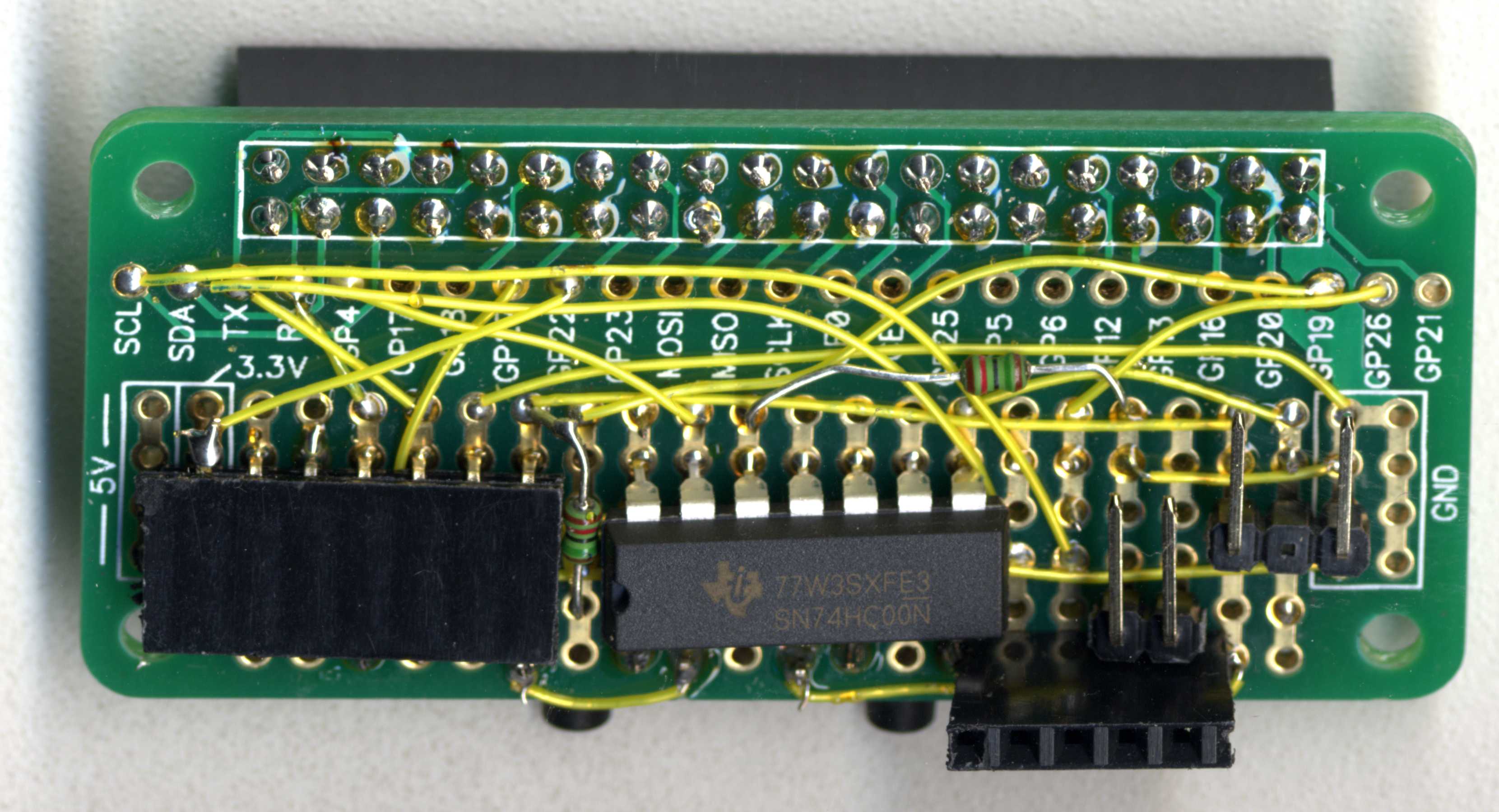
The layout of the Pi Zero breakout board to accommodate a GPS module, OLED display and power control circuitry requires a four pin SIL header (for the OLED display), a seven pin SIL header (for the GPS module) and various components, resistors, diodes etc. as well as a 74HC00 integrated circuit (which will operate on any voltage from 3V to 5.5V). The power control circuitry uses four NAND gates arranged as below:
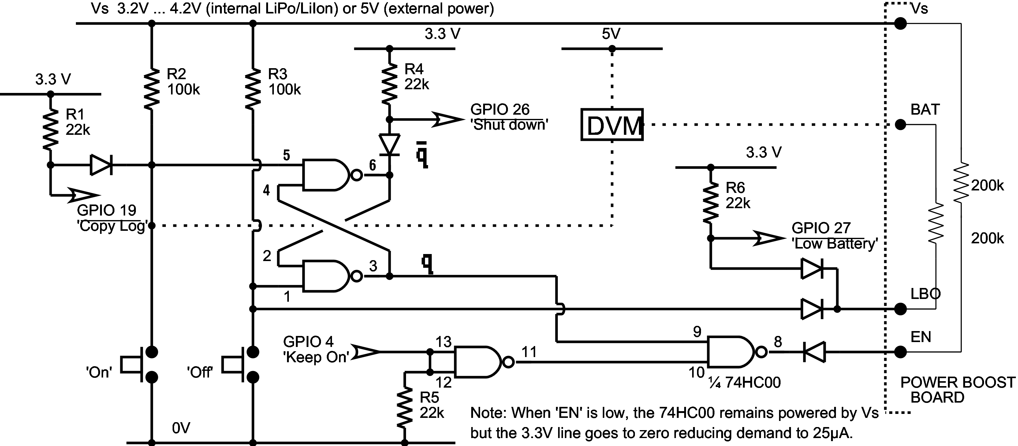
Here a latching circuit is used to respond to the ‘on’ and ‘off’ buttons: for power to be removed the flip-flop has to be ‘off’ (i.e. q high) AND GPIO 4 has to be low or high impedance. Thus power goes on as the ‘on’ button is pressed and is removed under software control after GPIO 26 has been sensed low. About 5s after power is applied, the boot process executes Choices:Boot.PreDesk.SetGPIO forcing GPIO 4 to output high. After sensing GPIO 26 low, logging is concluded, and a shutdown/restart cycle initiated which both updates the CMOS ‘last on’ time and resets the ROM, which takes GPIO 4 to high impedance, removing power.
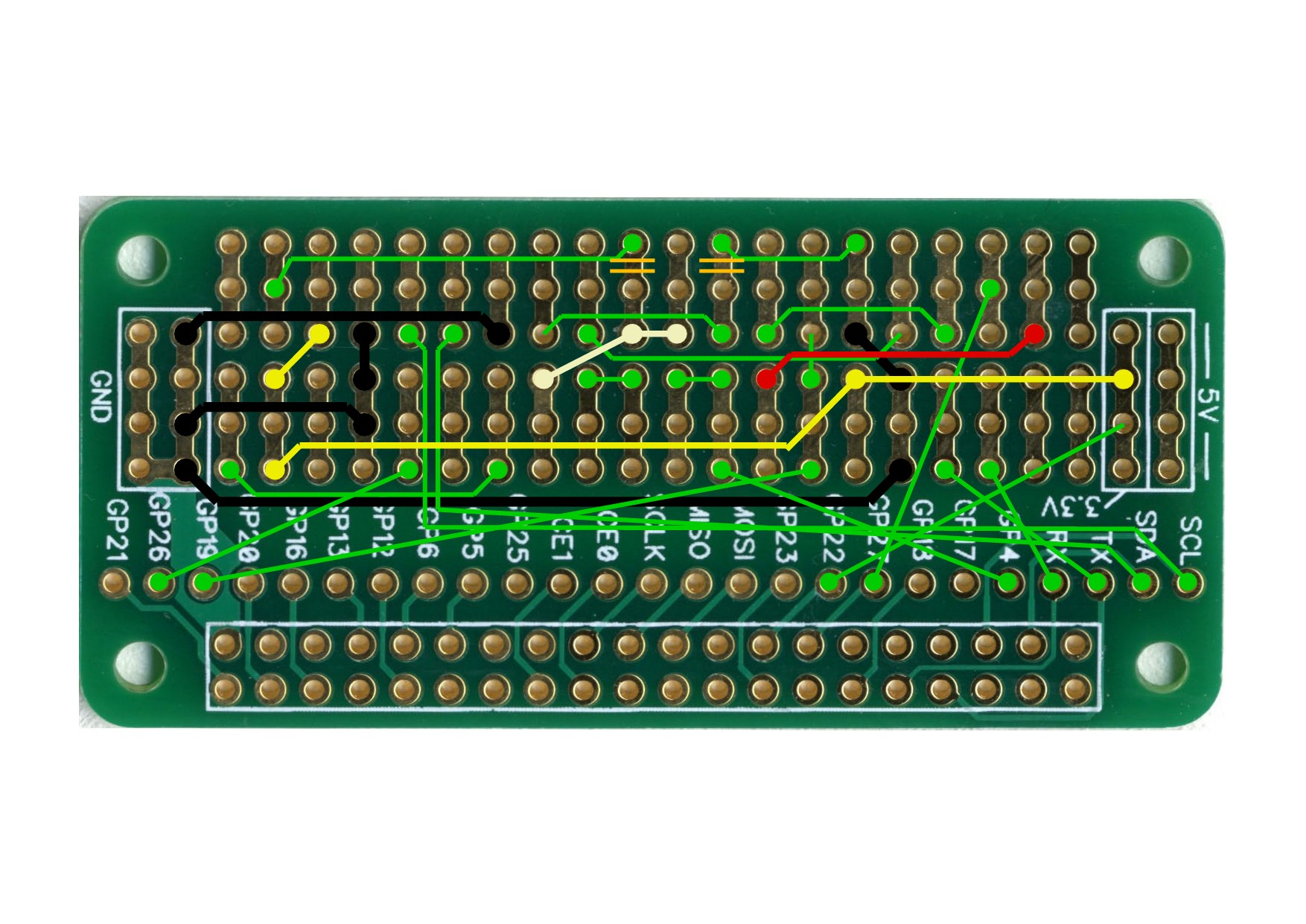
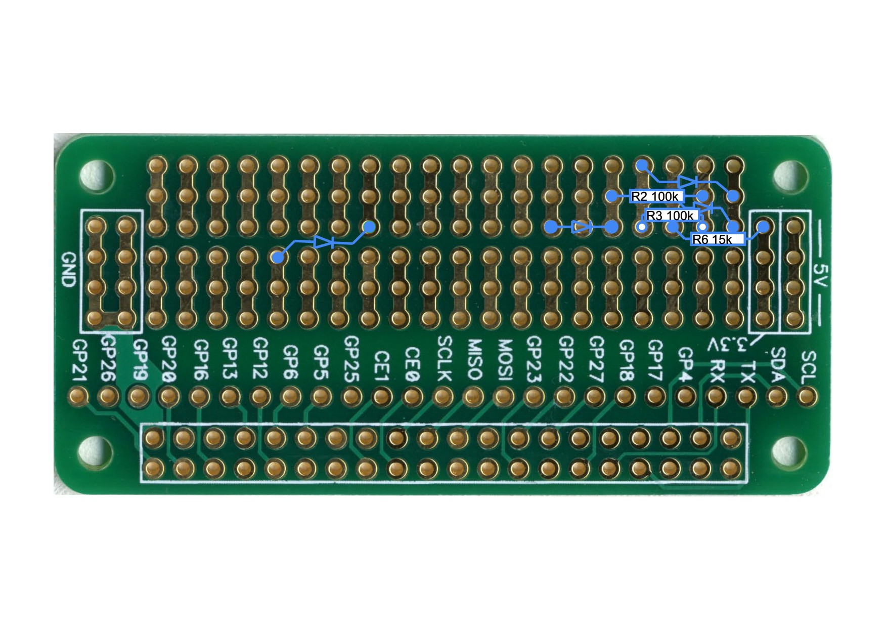
Laying out the breakout board ready for construction, with each set of components on a separate layer, greatly assists the soldering. Here is the desired layout for the board:
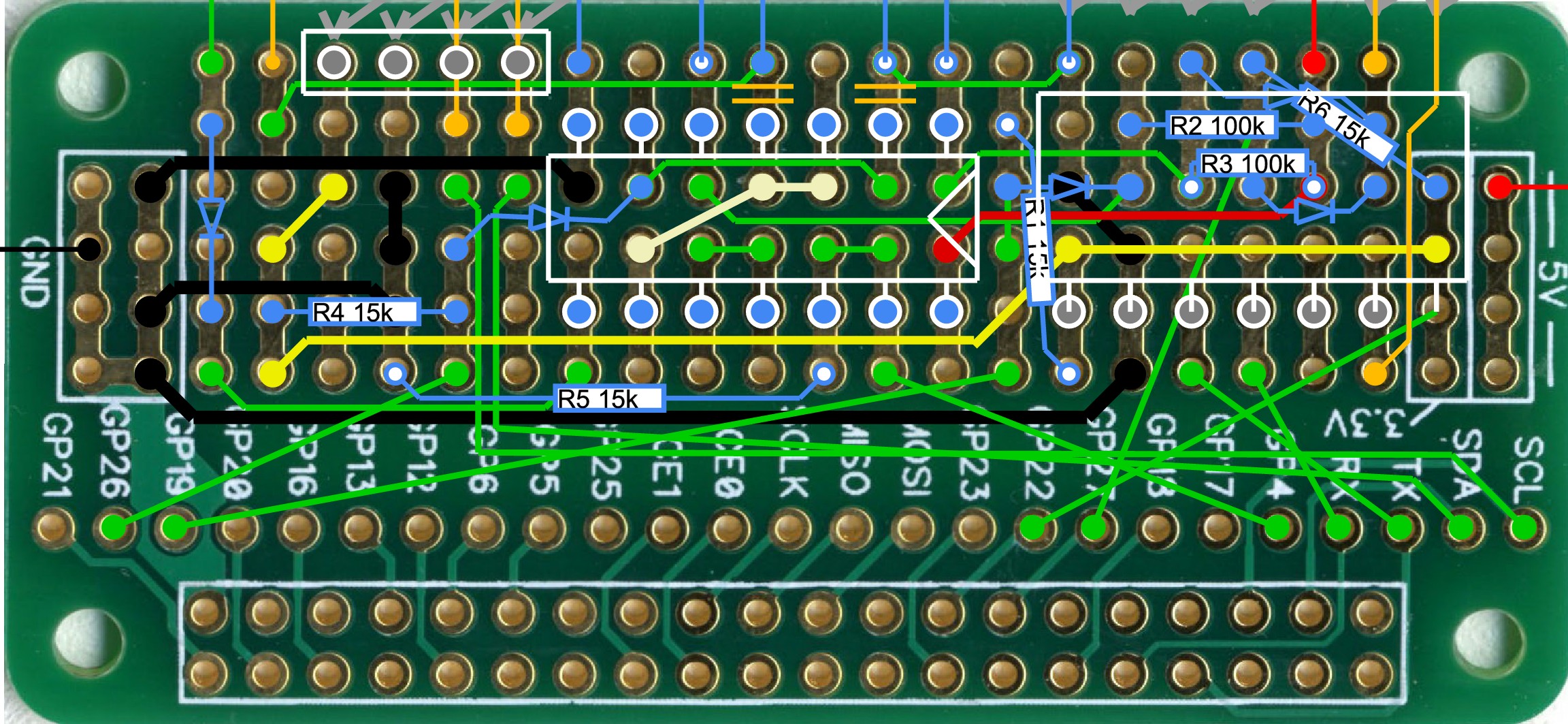
Component layout for the Pi Zero Breakout board.
Stage 1 is to cut a couple of tracks and solder some fine wire to connect some pads on the top surface of the board:
Stage 1.
Stage 2 is to add some components on the underside of the board:
Stage 2.

On completion of stage 2 it should look like this.
Stage 3 is to add some components on the top surface of the board:
Stage 3.
On completion of stage 3 it should look like this.
Stage 4 is to add the two SIL headers and the 74HC00 integrated circuit:
Stage 4.
On completion of stage 4 it should look like this.
At the end of stage 4 the board actually looks like this:
Looking at the underneath.
Looking at the top surface, there is provision for OLED displays with GND and VDD swopped over.
Stage 5 is to add the flying leads to the powerboost board and the ADC board:
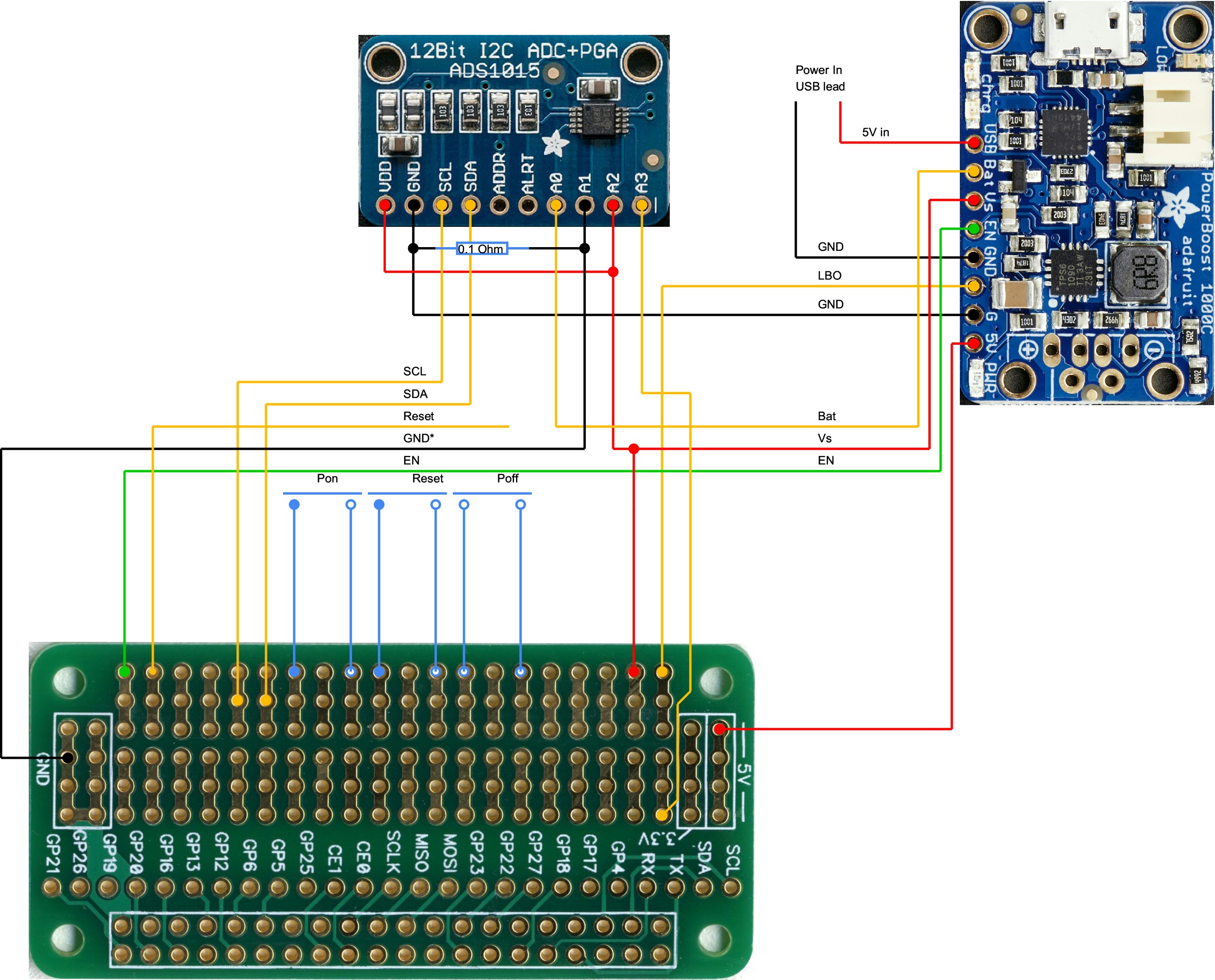
Stage 5.
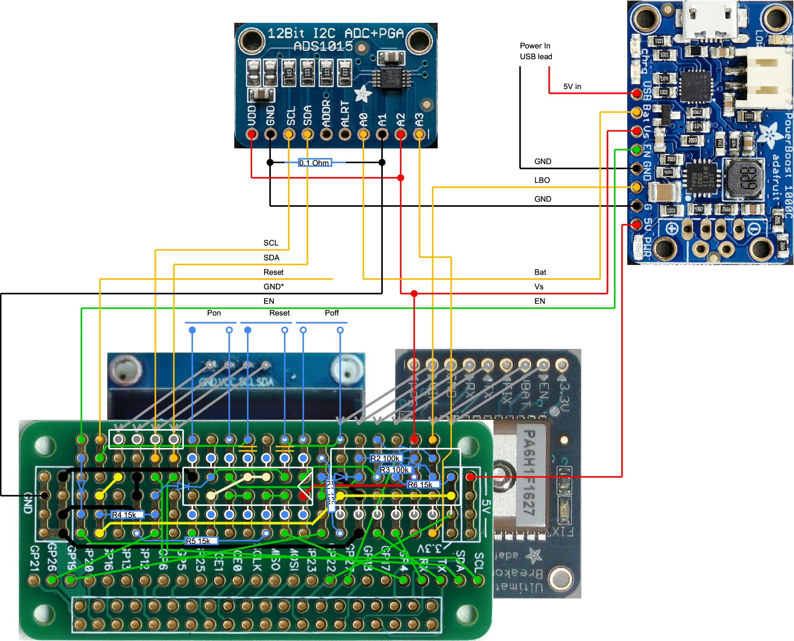
On completion of stage 5 it should look like this.
Battery endurance
The GPS unit consumes about 170mA at 5V and this means that a 4400mAh 3.7V battery should be able to power it for about 19 hours. During this time the Lithium Ion battery discharges from about 4.2V to about 3.3V. So I set about measuring battery voltage, time and current consumption using an ADC board to measure voltages with a 0.1 Ohm series resistor. The ADC board can measure 0.256V to 11 bit accuracy, which implies a current range of 0 to 2.56A with a resolution of ±1.25mA. For example the blue line on the graph below was plotted from time=0 at 4.2V to the time when it shut down, which proved to be after 9½ hours at 3.2V. On the graph it is plotted with shut down time at the left. The solid black and red lines were plotted in the same way, at different currents and with different batteries fitted.
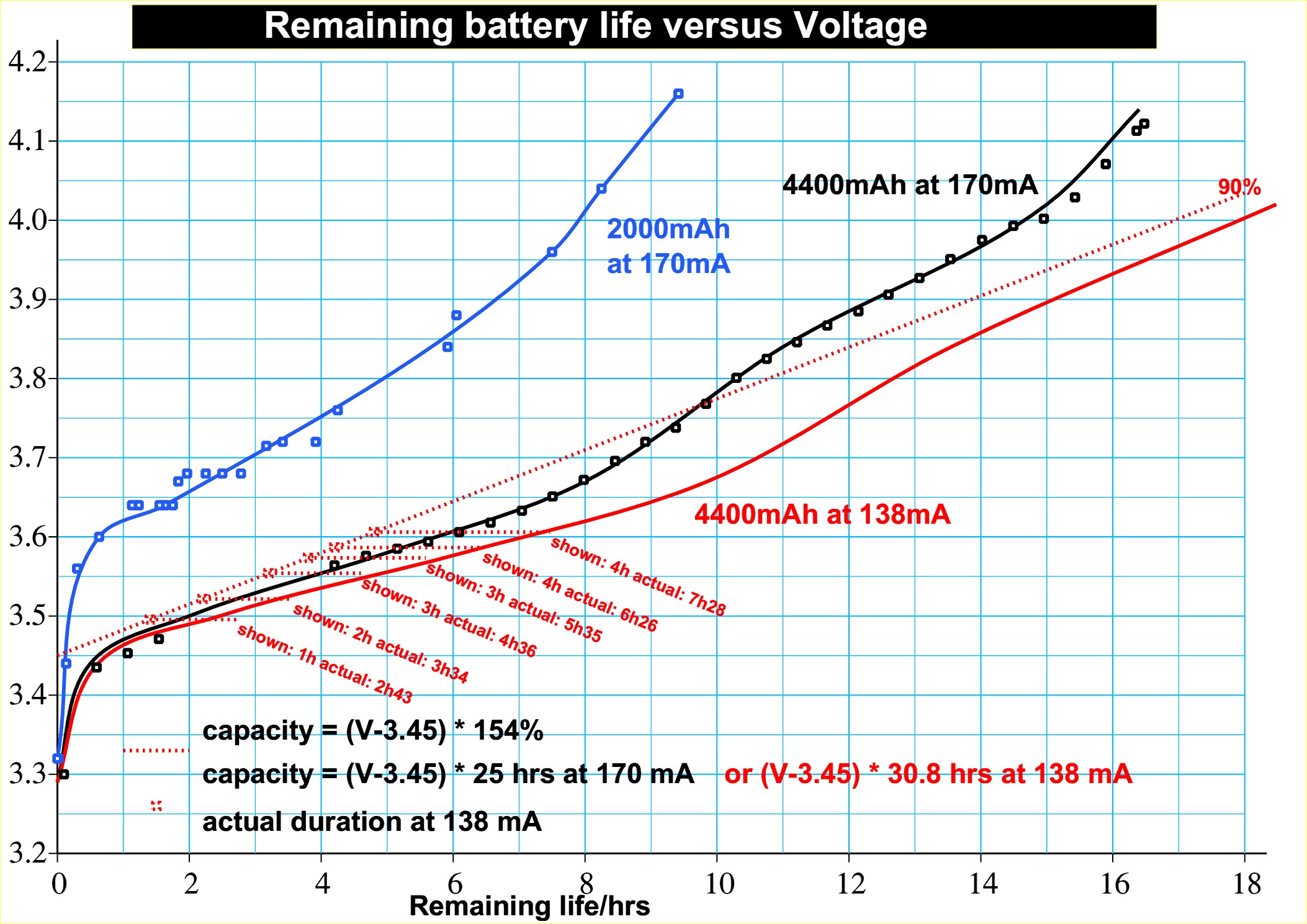
The dotted red line is a linear estimate of the remaining life, expressed as a percentage, for the red line. When expressed as a percentage it is independent of battery capacity and current consumption. At voltages above 4.2V it can be inferred that the battery is being charged and its capacity cannot be determined.
Case design
The case for the GPS unit is made from polycarbonate sheet, held together with brass BA screws. The design is printed onto sticky labels which are affixed to the protective plastic film on the strips of polycarbonate. They are cut to length and holes drilled where shown.
The holes are tapped for either 6BA or 8BA and the case screwed together.

The case still with sticky labels on to show where to drill the holes to mount the various circuit boards.
Data Logger
A further development of the concept is a data logger. This has been produced to monitor signalling circuits so that a precise sequence of relay operations can be logged. Eight inputs are scanned 1500 times a second and any changes of state are logged. The GPS module has gone, replaced by a simple real time clock card. Otherwise the software is very similar, with changes of state of any one of the eight inputs being the parameter that is being monitored rather than GPS location. The unit is designed to operate for weeks at a time, with regular visits to download data to a USB pen drive simply by pressing the 'ON & INFO' button. Making the device fault tolerant was quite tricky as there is no desktop display to show errors. (A desktop display is being created but no monitor is plugged in.)

Eight inputs plus three voltage-measuring inputs (approx. 0 to 30V with a resolution of 33mV). The terminal block can be unplugged.
More stuff and photos to follow.