 SVR S&T Dept.

SIGNALLING NOTES - Chris. Hall
We are making progress with the problems affecting the track circuit indications and arm repeaters between Bewdley South Down Distant and the signal box. On 22 April we loaded a drum of 27-core signalling cable into the Driving School coach and, using the 08 from Kidderminster, paid out 470 yards of cable from the end gangway between the Down Home and the Up Starting Signals before lunch when the gaps between trains were sufficient, with grateful thanks to Dave Phillips who guarded the train. On 23/24 April (non running days apart from a photo charter on the Monday) we hired a trench digging machine and buried the cable - the weather was good on the Monday but had deteriorated into heavy rain by the Tuesday. This was done without damaging the existing cables, the route of which we had scanned and marked with paint. During the work the existing cables were isolated and the links only reinstated at the end of each day to prove that all the circuits were operating normally. At times we were quite close to the existing cable! Over the next few weeks we will be terminating and testing the new cable and so by the time you read this, all should be in order again.
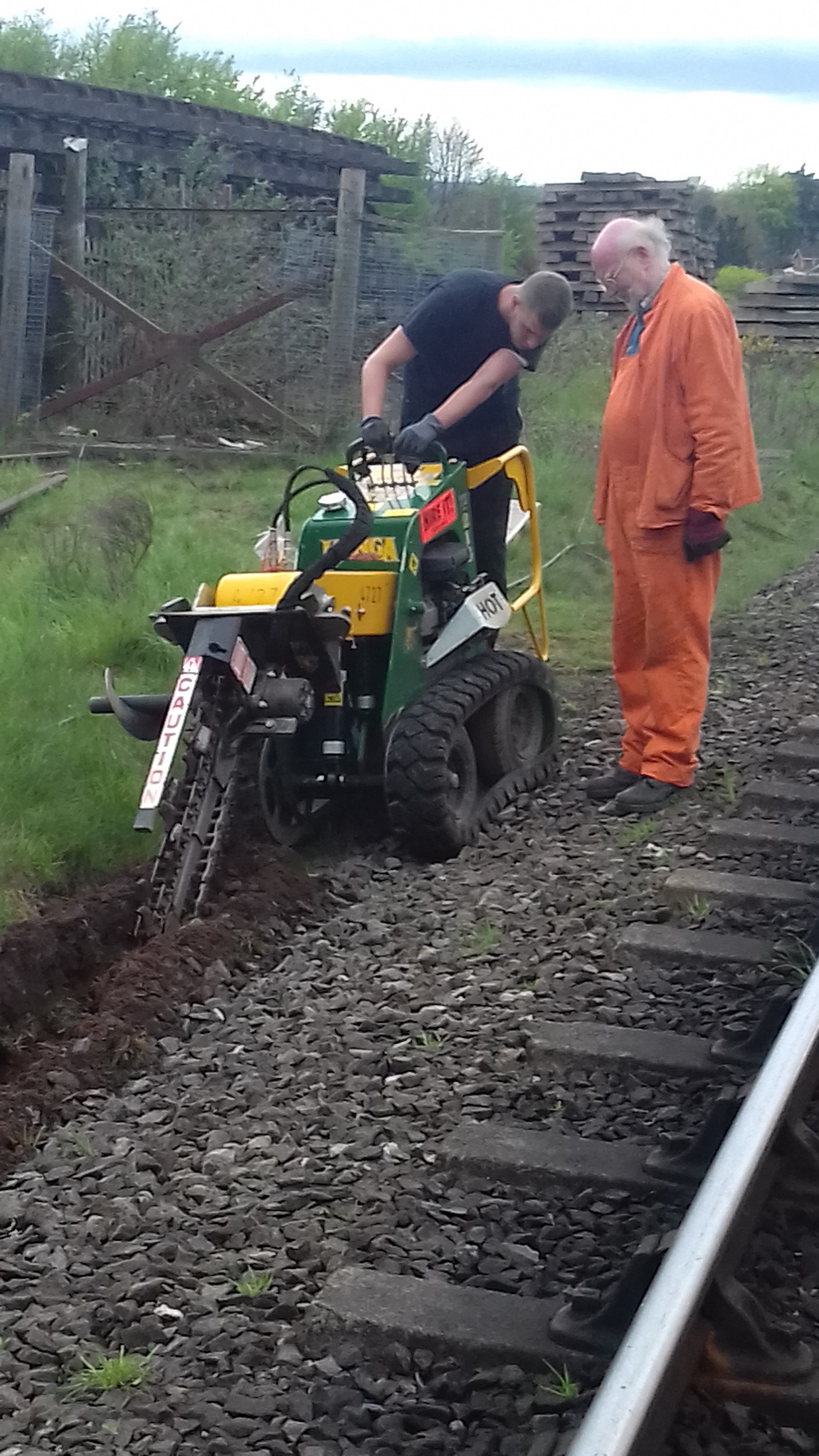 Bradley is making good progress with the trench digging machine on 23 April in fairly good weather, only a few inches further from the track than the route of the existing cables, Dave is looking for the paint marks on the ballast (the driver of the machine cannot see ahead, nor whether the digging arm is at the correct depth). [Photo: J.Phillips]
During February the extra stay-wire we had dug in for Bewdley North's Up Inner Homes bracket was connected and a road railer used to bring the signal to the fully vertical so that both stay wires could be tightened to hold it in place.
Other work has been ‘behind the scenes’ to prepare the wooden post from Highley’s Down Distant, which had been cut off at ground level to remove any rotten wood, for use as a replacement for the Down Starting Signal there after the main running season has finished. We managed to find all the wooden post castings and fittings we needed for this signal, some of which were seized and worn. Worn bearings were rebushed and a couple of new spindles will have to be made. The tapered post was reprofiled at the top so that the finial would fit correctly.
For some time now, we have been intending to replace some of the lever leads in Bewdley North. These show the number, name and pulling sequence for each lever and a small number were altered in the 1970s when the main to main trailing crossover and connection from Down Main to Back Road were removed. A few more were altered in the 1990s when working distants were introduced and levers 1 to 3 were shuffled to 2 to 4 and lever 37 became 36, as well as other changes. The alterations to the lever leads in the 1990s were done on a temporary basis, with thin metal plates and computer-printed gold labels rather than brass. Many of the leads remained original, including lever 14 which originally bolted two points and therefore listed pulling sequences for both up and down movements.
We now have 22 brass lever leads to fit: a few levers have holes drilled a little higher or lower than the others but the new leads will be fitted, so far as possible, to be exactly lined up. On 29 April we managed to mark up and fit new leads to levers 1, 3, 4, 6, 7, 8, 9, 10, 15 and 16. Several levers had to be drilled to take a second lug and leads for 17 and 18 were ready to fit when the 17/64Ģ drill bit started to go blunt. This meant that a day’s work had got just a little more than half way through the fitting. You may wonder how a hole is drilled in a lever at the right place. A few levers do already have a hole drilled at the correct spacing for medium and long leads (which both have a second lug) and we first drill a hole in the top lug of the lead so that the lead is at precisely the right height. The second lug is drilled to suit a lever which already has a second hole (to maintain standard spacing) and then used to mark up the second hole for the intended lever.
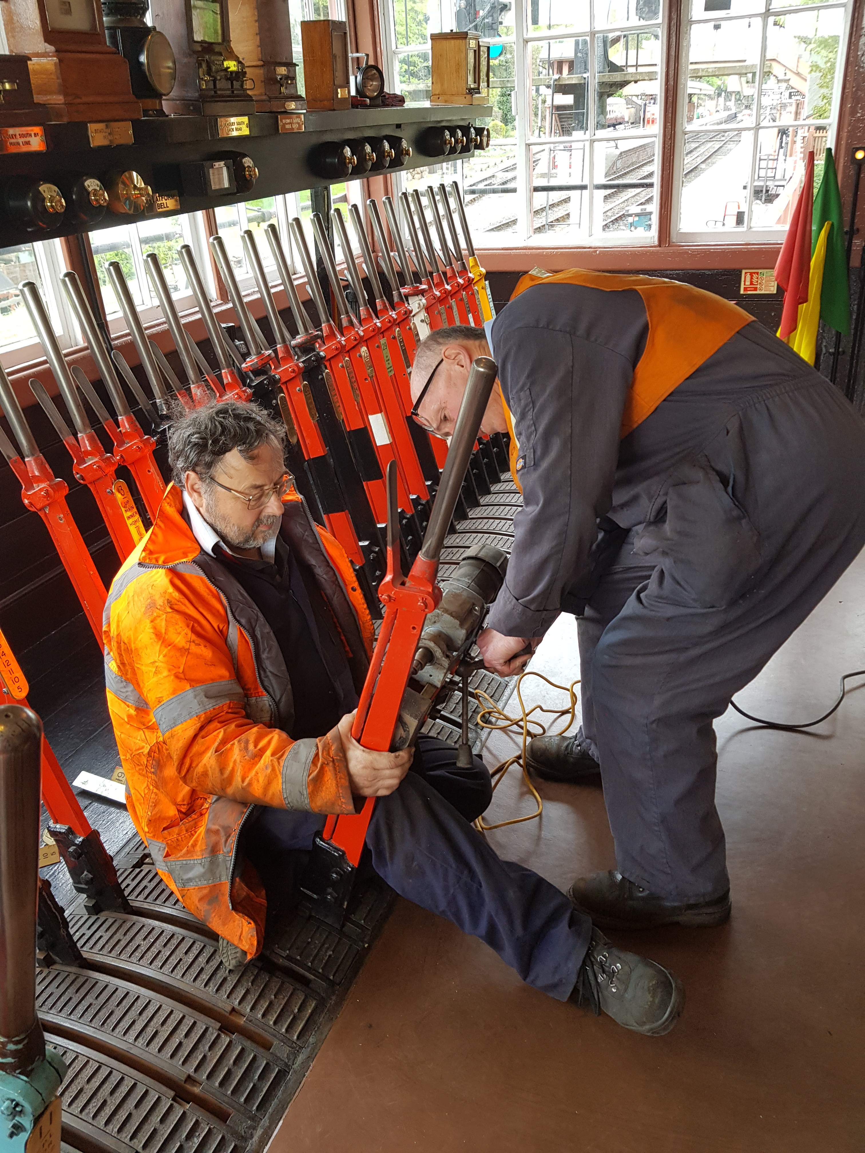 Drilling a hole in a lever - just there! The magnetic drill is so useful for this sort of work. In a gap between trains, we were able to get 17 lever in a position to drill it. [Photo: Dave Stowell]
The picture shows lever 17 being drilled using a magnetic drill clamped to the lever, (just before the drill went blunt). Lever 16 required the two adjacent levers (15 and 14) reverse but the lugs were on the correct side so that we didn’t have to disarrange any mechanical locking to get the drill into place. That might pose a problem later for 18 (which requires 21 reverse) and 23 (which requires 24 reverse) but we can probably drill those with the lever clamped in the mid-stroke position. Fortunately the leads for 24 and 26 points (which usually have stock stabled on them) and for discs 25 and 27 (which read over them) do not need replacement.
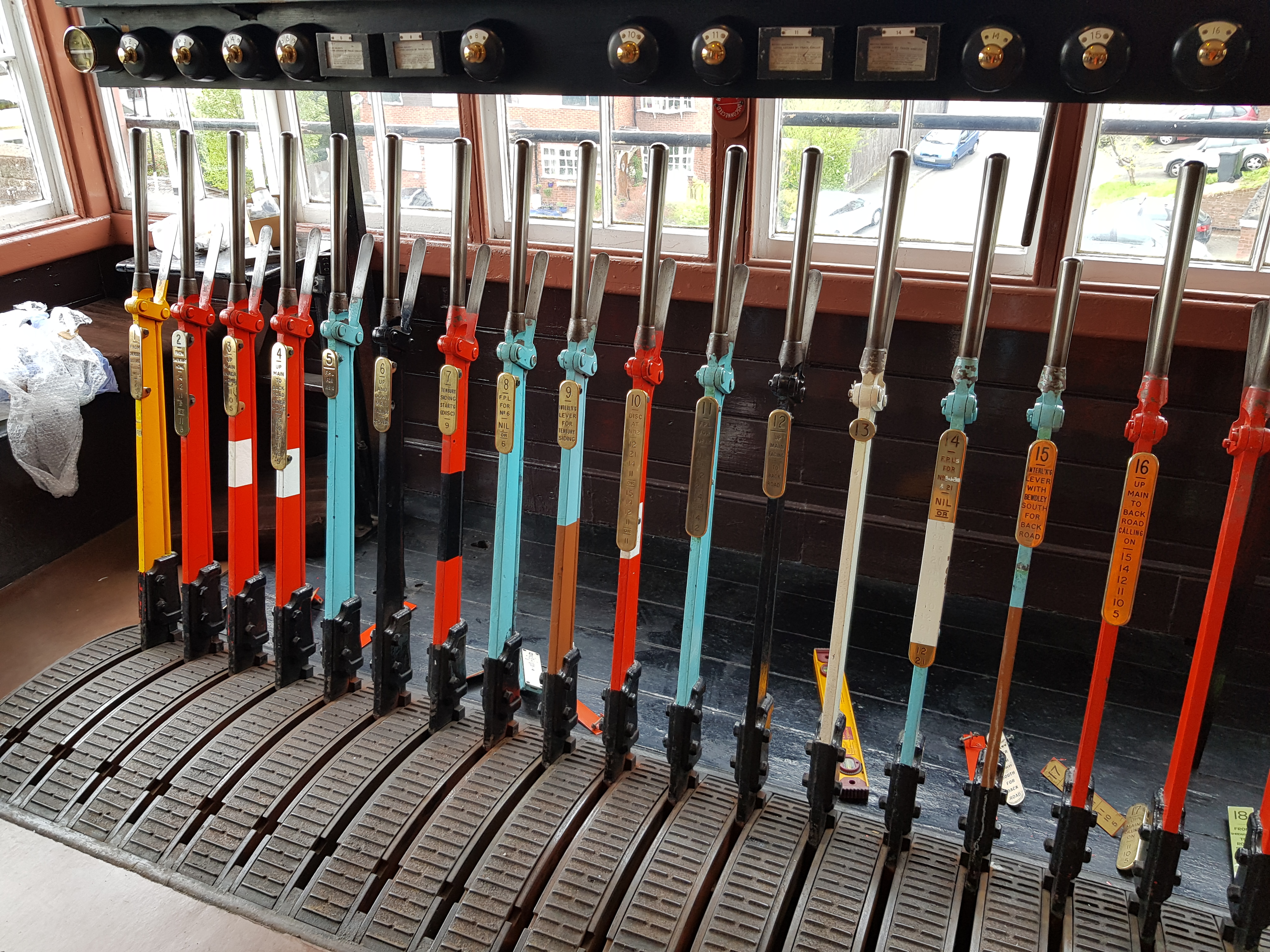 The new leads fitted to levers 1 to 16 (the leads on levers 2, 5 and 11 to 14 are the original leads from GWR/BR(WR) days) on 29 April. They were then removed and the temporary leads refitted so that the backs of the new leads could be painted. [Photo: Dave Stowell]
In March we spent a day at Bridgnorth rectifying some problems reported the previous weekend during the Spring Gala (some of which were probably related to the poor weather conditions). We also found a baked power supply unit which was barely providing sufficient output to light the signal lamps at the south end of the station. A replacement unit was fitted the following weekend.
A final reminder that this article, as well as other information on Signal Engineering, can be viewed in full colour here on the unofficial Signal Engineering web site.