 SVR S&T Dept.

SIGNALLING NOTES - Chris. Hall
In the last few months we have been rather busy. In addition to the regular signal maintenance we do routinely on the railway we have a number of other projects Éon the goĹ along with training.
Foley ParkOn Tuesday 3rd September the location cupboard at Foley Park was planted. As can be seen from the photo, it houses a telephone, local indication of the main line points detection and a key release instrument to release an AnnettĹs key to unlock the ground frame with full Éshut-inĹ facilities. On Tuesday 17th September trenching between the location cabinet at the Up Homes berth track (54) and the ground frame at Foley Park (53A) was dug in and cables laid. At a later date the cabling between locations 55 and 56 will need to be tested and the new location at the ground frame commissioned and brought into use: this will offer local indication to operational staff to confirm that the ground frame has been correctly restored to normal after being unlocked (using the occupation key) and has a telephone that communicates with Kidderminster box. Further work in the signal box is needed before the key release instrument can be brought into use.
 The new location cupboard at Foley Park. From left to right the group comprises Dave Stowell, Brian Graystone, John Smith and Dave Evans. [Photo: B. Graystone]
 What the Traffic Shunter will see: a telephone, indication that the points have been correctly restored to ÉnormalĹ and a push button to turn the light on. [Photo: ]
On Sunday 1st September the mounting for the new circuit controller for lever 55 at Kidderminster was measured up: this bolts to the frame and to the concrete floor and required a frame support to be moved one space left. Point rodding, that universal and versatile standby, was used to fill the gap between the mounting and the floor.
A new lever 55 has been installed which, after several more monthĹs work, will release the ground frame during traffic hours. The lever is painted blue over brown (its first function will be to release the FPL at Foley Park and levers for FPLs are coloured blue). The lever now has a circuit controller, cam box and tappet connected but extensive wiring changes and at least six new relays will be required and these are currently just at the planning stage.
Once complete, the following operations will be supported: an Up or a Down train may stop at Foley Park and ask for a GF release; a train may ask to be shut in with the single line clear for normal traffic to resume; a train may ask to be let out of the sidings onto the single line (just to shunt or to leave as an Up or Down train) or seek permission to resume its journey after shunting the sidings.
 Lifting the floor plates makes one wonder whether there is room for another lever! [Photo: ]
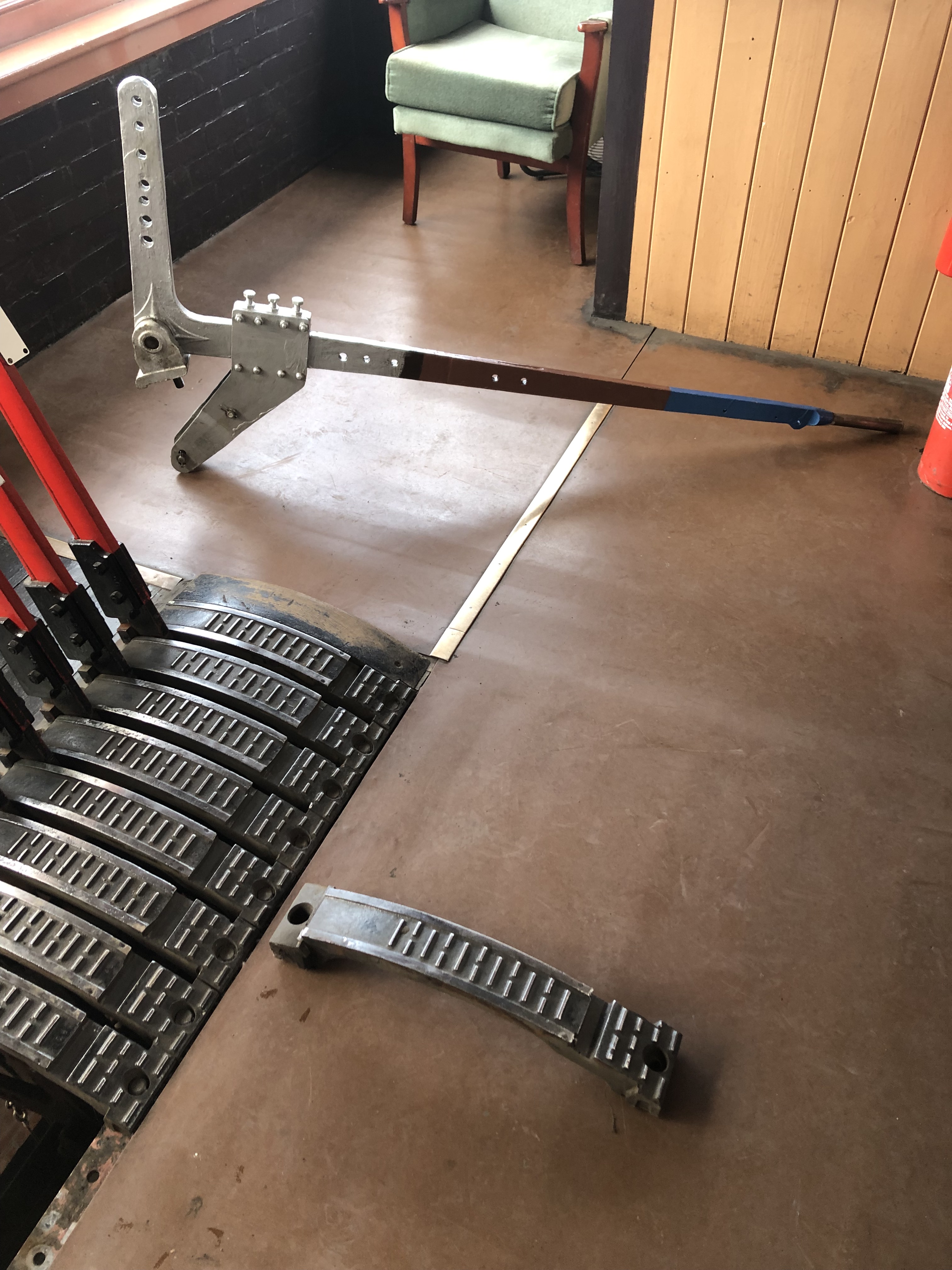 The new lever has both a tail (which we wonĹt use) and an extension piece (to drive the circuit controller). This makes it difficult to manoeuvre! [Photo: ]
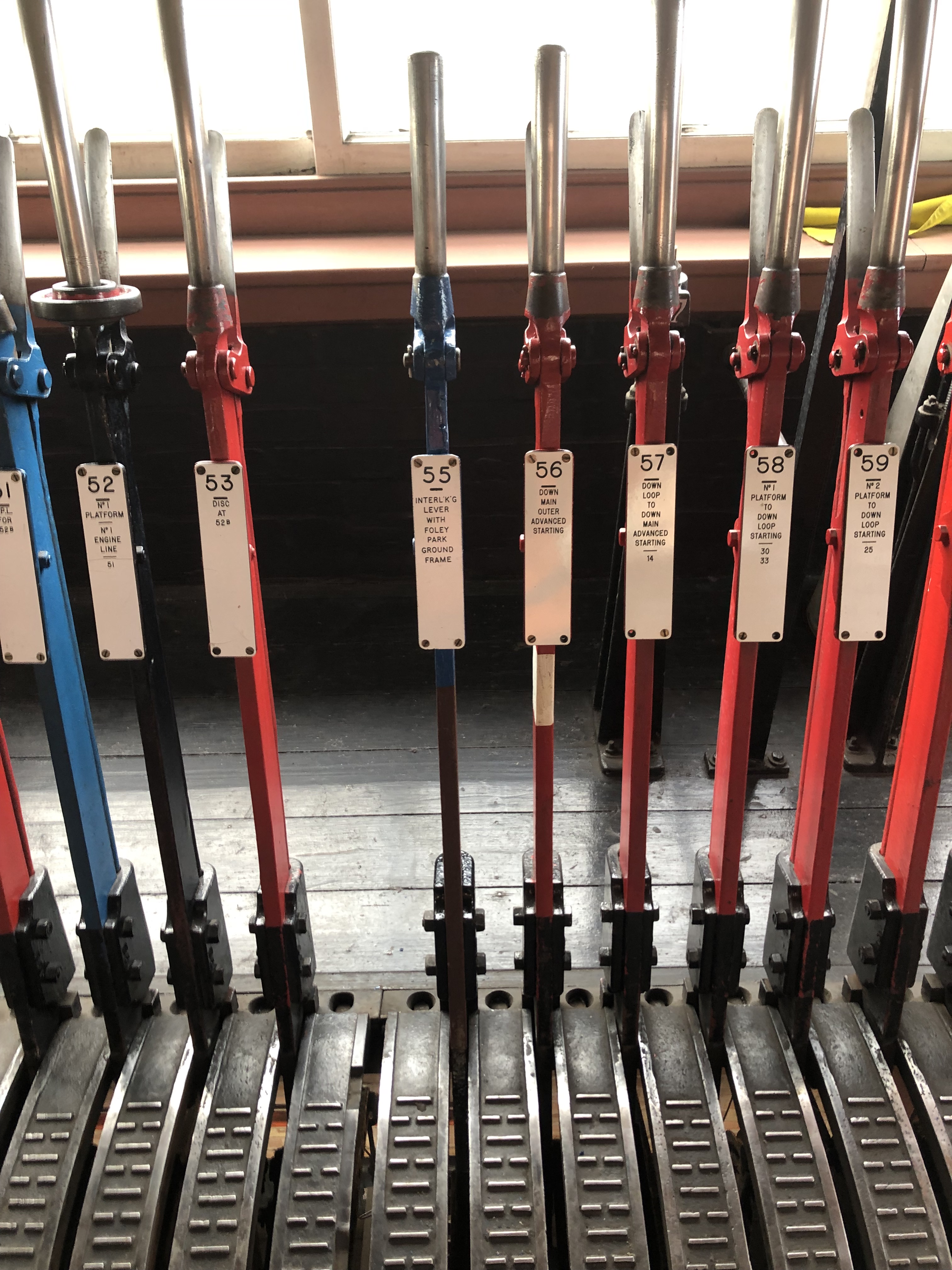 As always little to see from the operating floor but the new lever is there, as well as a cam box, tappet and circuit controller. [Photos: B. Graystone]
On Sunday 15th September we spent most of the day removing and renewing a worn compensator on 30 points at Kidderminster, arranging a suitable time between trains with the signalman. Some effort was required to remove bolts that had not been disturbed for over forty years - the technique is to undo then one at a time, clean then and replace them so that the disconnection time is minimised (and does not intrude onto our lunch break).
On Sunday 13th October we spent most of the day drilling two żĽ holes in the concrete floor for rawl bolts to secure the circuit controller for lever 55. We also made up a locking bar for the mechanical locking on lever 55.
HighleyOn Sunday 4th August we took advantage of the availability of the milling machine to manufacture fourteen locking studs using the tool made in 1999 for the work we did at Williton. On completion the tool had worn rather badly and so we will need to manufacture another one at some point. This is a highly skilled job which may take several attempts.
On Sunday 22nd September we took advantage of the frequent train service to get from Bewdley to Kidderminster to find a suitable lever contact box in our stores for lever 5 at Highley. The frame at Highley is a non-standard conversion to 5-bar locking so we discovered when we took it to Highley that it would not fit! Returning to Kidderminster we sourced a different contact box that should fit. The contact box is required so that an electrical release for the disc signal at the north end headshunt is generated when 5 points are normal for moves into the headshunt. Initially we thought that a relay would be required as three sets of contacts would be required but we were able to squeeze two normal and one reverse contacts onto a four finger slide, avoiding the need for an extra relay.
On a further excursion to Highley on Wednesday 25th September (a non-running day) Paul and myself marked up tappets 1 and 10 and a whole dayÉs machining on Sunday 29th September saw the ports cut before the milling machine was relinquished for about six weeksÉ work on loco components by 1501/2047 group. Hopefully we will have the use of the milling machine again by the weekend of 9th/10th November to machine the remaining tappets, which canÉt be removed until the possession starts.
The condition was fitted to the new tappet 10 on Sunday 6th October after a search at Kidderminster for the right bits of kit and has been welded to the tappet. On Sunday 20th October a revised contact slide was fitted to lever 5 at Highley which completes the preparatory work for the possession on 9th November.
 The clever solution - squeezing three contacts into a space for two [Photo: Paul Marshall]
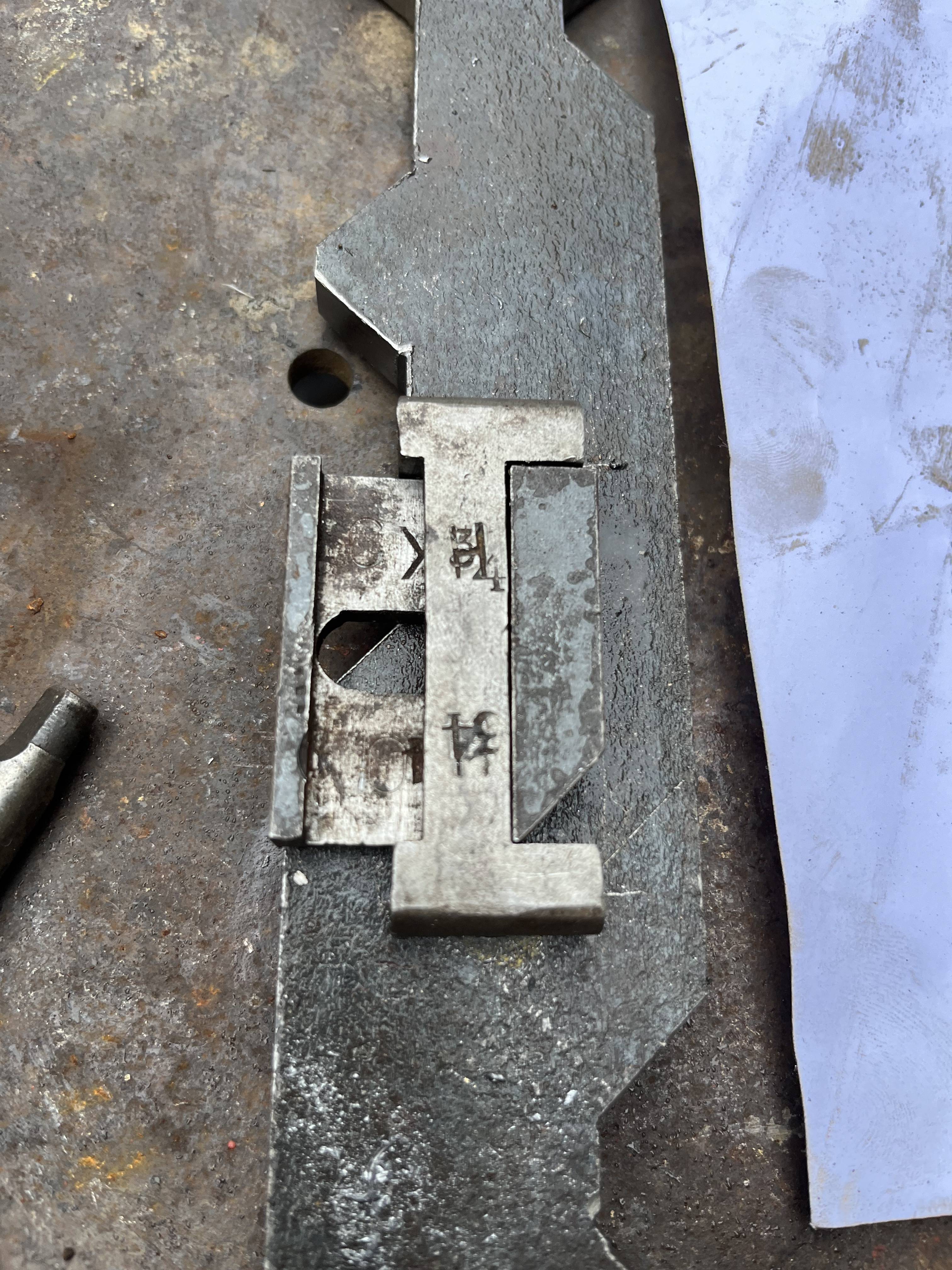 What is a ÉconditionĹ? It is a sliding lock that transmits movment between locks each side of the tappet but only (here) when the lever is reverse. [Photo: C. K. Hall]
 The bell to annunciate the approach of a Down train at Highely. [Photo: B. Graystone]
 The wire winding machinery in action. [Photo: B. Graystone]
 The re-wound coil plus two spares. [Photo: B. Graystone]
We have designed and installed a train approaching warning bell in Highley signal box. The system uses a treadle switch mounted on the track which gets operated by passing train wheels on a Down train to trigger a bell for a few seconds in the box. Diesels do not seem to be able to generate the tell-tale puff of steam above the trees that marks the arrival of a Down train.
Other WorkWe were asked for help by Gary from the Carriage and Wagon Department recently. They had a solenoid coil which had failed open circuit,waggon it is used in the electrical system on the carriages which controls the lighting. Brian used our coil winding machine to re-wind the 150W coil, using 0.28mm diameter copper wire, onto the original metal bobbin. He then wound two new coils onto plastic bobbins giving Gary some spares for any future failures.
TrainingMatt and Brian recently received training on the operation of the railwayĹs engraving machine. This was very useful as we have a number of engraving jobs to be done. The first item to be engraved was the AnnettĹs key for Foley Park ground frame. We also engraved four new tokens for the Hampton Loade to Highley section. Then we engraved two signal lever signs for the number one lever at Highley and the new 55 lever at Kidderminster.
 The AnnettĹs key for Foley Park. [Photo: B. Graystone]
 a new token (one of four) for the Hampton Loade-Highley section. [Photo: B. Graystone]
 two new lever leads - one for Highley and one for Kidderminster. [Photo: B. Graystone]
 Brian in action on the engraving machine machining the lever lead for lever 1 at Highley. [Photo: D. Salter]
A reminder that this article, as well as other information on Signal Engineering, can be viewed in full colour here on the unofficial Signal Engineering web site.