 SVR S&T Dept.

SIGNALLING NOTES - Chris. Hall
Just after sending off the last set of Signalling Notes to the Editor, a lot of things got nicely finished off so I thought I had better write them up at the end of August while they were still fresh in my mind. It was then fairly simple to update the text to reflect our activities in September and October.
The hot weather which had persisted in late July and early August had caused problems with the newly replaced pointwork at the south end of both Hampton Loade (reported last year) and Arley. In both cases excessive expansion of one of the stock rails, transmitted to the switch rail via gauge ties, had caused the FPL (facing point lock) stretcher (a rather substantial bit of steelwork 15mm by 76mm in cross-section) to press hard against the FPL casting, making the points difficult to close up. At Arley this had significantly increased the stresses on the compensator causing it to seize up, making the points even heavier to work. Contributory factors included chemicals leaching out of the platform (a steel cover has been fitted to deflect these) and the design of brand new B.R. compensators (which have tight clearances and awkward access underneath a platform overhang making the introduction of grease very difficult).
We had fitted a brand new compensator when the points and rodding run were renewed as part of the drainage work at Arley and had replaced this with another brand new compensator a few years ago. On examination on 22nd July, the compensator was found, again, to be seized making the points heavy to work. We had a replacement in stock and this was fitted on 29th July which partially cured the problem.
As reported in previous articles, we have been struggling with intermittent faults on the single line track circuits between Bewdley and Kidderminster. This is an example of the difficulties which have to be overcome. The cabling for these circuits was obtained from a signalling contractor after being transported to Hong Kong and back more than thirty years ago and had thus endured a round the world trip before being buried in the ballast. Probably disturbed a few years ago, difficulties were being experienced with the reliability of ‘AA’ track circuit and other circuits in this cable.
This track circuit ‘AA’ is indicated in both Bewdley South and Kidderminster boxes but in each case is shown combined with other single line track circuits (in Bewdley South with (KR)AB and (KR)AC and in Kidderminster with (BS)1AT and (BS)30T so that any fault reporting requires close collaboration of the signalmen). It is much more complex than this in its implementation as AA track circuit is, in fact, three separate track circuits ‘AA1’, ‘AA2’ and ‘AA3’. An improvement in about 2010 was the introduction of a separate indication in Bewdley South of ‘AA2’ track circuit, the tunnel track, so that any examination of the line consequent upon a track circuit failure could be undertaken in the knowledge of whether the tunnel itself was clear. This would allow use of a passenger train to examine the line rather than mandate the use a light engine and thus avoid the associated delays.
Analysis of an intermittent fault (or one that is the result of two or more separate problems) is always difficult: this was both. Proving that the affected track circuit was actually ‘AA1’ was only possible on 1st July. A more detailed examination was then able to show that the fault was not with the track circuit ‘AA1’ relay (AA1TR) itself but with the repeat circuit (AA1TPR) where any problems with cable degradation were being exacerbated by verdegris on the relay base and dirty spade contacts. Replacement of the affected cable (between the Home and Starter), cleaning of the relay base and replacement of the spade connectors now appears to have cured this problem.
At this stage Bewdley South Down Distant remained booked off and fixed at Caution as testing of the 110V power cable from the Home Signal berth track circuit to the Distant showed a cable fault reducing the power available below that required to operate the signal battery machine reliably. It seems unreasonable to suggest that the P-Way work to fit breather switches at the Bewdley end of the tunnel during relaying could have caused the cable fault, so I won’t suggest that.
By using spare cores in another cable the fault was bypassed on 16 September and Bewdley South’s Distant was later booked back on, just in time for the Autumn Gala. Frustratingly an intermittent fault on the arm indication of Bewdley South’s Down Home Signal had vanished so despite spending most of the day there on 16th, there was no fault to trace. The fault recurred on 5 October during the Diesel Gala and it was traced to the 5-core cable from the location cupboard to the signal arm repeater. This was temporarily bypassed within a few hours by the paid staff allowing normal working to resume. The arm indication on this signal affects the single line controls and the Up Home Signals.
Reports that no. 4 signal at Bridgnorth (Platform 1 to Hollybush Road) was not returning reliably to Danger have identified two problems: a signal wire wheel has been found with a seized pivot pin and has been replaced to improve the ability to lubricate the pin. An adjustment has also been made to the route indicator slides, which occasionally jam. In fact on 12th August we replaced two signal wire wheels on the run to no. 4 signal.
We have drawn up a list of work on the north end crossover, rodding run, detection and spring assister at Bridgnorth, the latter in collaboration with the Permanent Way as soon as this work can be scheduled. On 12th August we disconnected 19 and 29 points to examine the condition of the various cranks and compensators. We had already brought one ‘low’ and one ‘high’ accommodating crank, two adjustable cranks and a compensator, hoping that these would be sufficient. We found that two further ‘low’ accommodating cranks would be needed (now delivered to site) but the ‘high’ crank and the compensator would not be required, as replacing worn pins on these proved a suufficient solution. See the picture above where the different types of cranks are illustrated.
 To turn a rodding run through 90° accommodating cranks are used, alternate ‘high’ and ‘low’ cranks allow 4″ of movement without fouling. The drive to the points uses an adjustable crank to allow for any lost motion. Both types are shown here. [Photo: C. K. Hall]
We were able to replace two full lengths of rodding (each eighteen feet long) on 29 points, the crossover at the north end, which were slightly buckled. The detection rod on 27 points (the spring traps, see photograph) was an interesting shape making adjustment difficult and we made up a replacement from new end pieces cutting a length of point rodding to suit. We were unable to fit this that day as the insulation that came with the one end was for a 1.25� hole and the hole in the extension piece was 1.125�. We made up new nylon insulation washers and fitted the new rod on 26th August. The ring spanner in the photograph is not broken: it is designed as a split ring so that it can be slipped over the threaded section of bar.
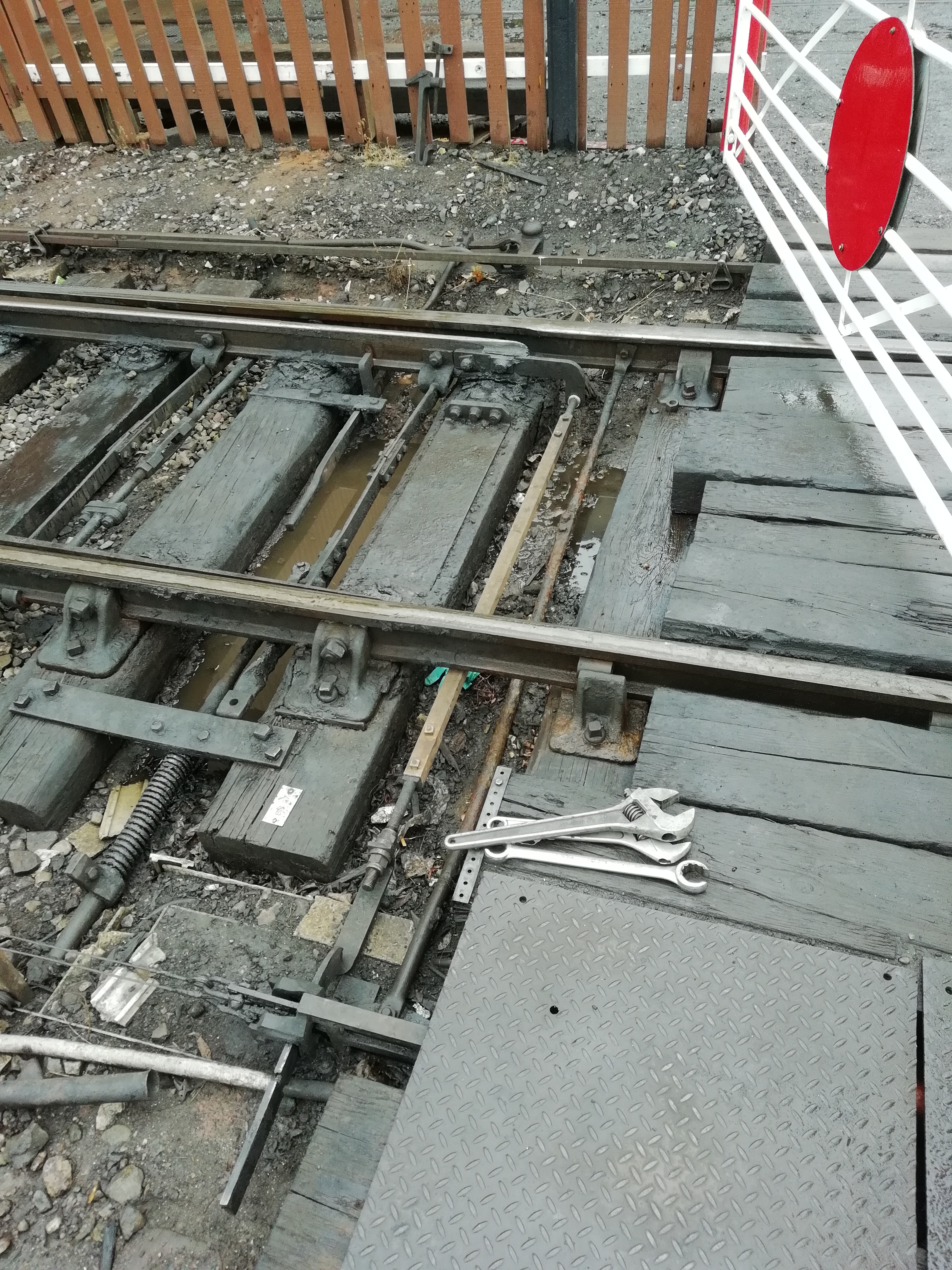 The spring trap points at the north end of Bridgnorth on 26th August 2018. Three beds have been dug out by the P-Way to allow the sleepers to be replaced and the one remaining insulated gauge tie to be removed. The other sleepers have already been replaced but the last two have some of our equipment attached and so will have to be a joint effort. [Photo: J. Smith]
The photograph of the trap points provides a good illustration of detection: the detection casting (which is at the bottom of the photograph, partially covered by the large steel plate) contains two signal wire slides and is firmly attached to the further stock rail. The switch rail has an extension piece to which the new detection rod is attached with nylon insulating washers. This rod is attached using a threaded joint with spherical washers to the detection slide - this provides adjustment. The slots in the detection slide can be seen and these only allow the signal wire slide to pass through if the switch blade is correctly closed up.
On completion of this work at Bridgnorth, a significant improvement and refurbishment at this location will have been completed and our attention will move southward to make the same improvements along the line. Work ‘behind the scenes’ preparing for replacement of two signals, Highley’s Down Starting Signal and Bridgnorth’s Headshunt to Yard Disc Signal continues.
Northwood Crossing has been reported on several occasions as not showing the Driver’s white light (meaning the train has to stop and be hand-signalled over the crossing) or as not shutting down until well after the train has departed. This has reinforced the need for some sort of monitoring equipment for faults that are difficult to trace (first identified as the problems with ‘AA1’ track circuit proved difficult to diagnose).
I had already developed a portable GPS speedometer which I had used on various railway (and car) trips to create a log of the journey which could be played back afterwards. With only modest changes this could form the basis of a data logger which would be connected mainly to unused spare contacts and provide a detailed log of the sequence of operations with each change of state precisely timed. The GPS speedometer is under evaluation by SVR and has been successfully tested on at least two trips, one on a locomotive fitted with a speedometer.
 The GPS speedometer - the unit is 3½″ x 2½″ x 2″ and has an ‘on’ and ‘off’ button, a connection for an external GPS aerial and a USB port which allows journey logs to be downloaded to a pen drive. The battery lasts for about 17 hours between charges and the remaining battery life (plus milepost mileage and odometer) can be displayed whilst stationary. A modified unit without the GPS module can monitor eight inputs and three voltages providing sampling about 1500 times per second: this also allows daily logs to be downloaded. [Photo: C. K. Hall]
The purpose of the data logger would be to provide more detailed information about the operation of a particular function so that much more rapid diagnosis of any reported fault could be undertaken once that function had been identified as requiring particular attention. Its first use is likely to be at Northwood Crossing to confirm that we have cleared up a fault which affected its ability to reset itself correctly after the passage of a train.
The age profile of the volunteer staff in the S&T Department is rising year by year and we are keen to attract existing volunteers with an operational role to join us. The job is an interesting and demanding one and full training would be provided to anyone willing to take on the extra reponsibility. The job offers enormous variety and we wouild be pleased to show off what we do to anyone with a genuine interest. Please feel free to come along to Bewdley buffet for a Sunday breakfast to meet the team.
A final reminder that this article, as well as other information on Signal Engineering, can be viewed in full colour here on the unofficial Signal Engineering web site. Further information on the GPS speedometer can be seen here and on the data logger here and in a news item on iconbar here.