 S & T Notes - issue 133
 S & T Notes - issue 133
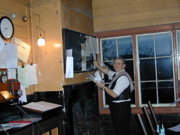
On the Wednesday evening with testing complete and with many levers renumbered, a new set of 'footnotes' (local box instructions) has been prepared. After an exhausting lever pulling session Russell Maiden takes great delight in removing the old box instructions.
SIGNALLING NOTES - Chris. Hall
These notes cover the period February, March, April and May 2000 during which the Department has completed phase 1 of the work at Bewdley North. Not much work took place in May as many of the S&T were on a canal boat that month. The new location cupboard for Bridgnorth, the installation of which I have been optimistically predicting in previous sets of notes, has been completed and work on site to prepare for its installation is well advanced. Amongst all this the routine maintenance has been kept fairly [check maintenance schedule] well up to date.
Phase 1 of the Bewdley North work was a large project which made a strong call upon the resources of the Department. This phase of the work was planned to take place over a four day period starting on Easter Sunday and comprised the necessary electrical and mechanical work to shuffle levers at the high and the low end of the frame to release levers 1 and 37 for working the distant signals as well as making provision for two new signals. It may seem illogical to plan work over a busy weekend but volunteer availability for both S&T and for additional staff such as handsignalmen is at its highest. A tableĀD service also gives the greatest margin at Bewdley for recovery from delays caused by handsignalling.
Large projects like these are a good opportunity for newer members of the Department to see and understand how the inner workings of a signalbox are taken apart and put back together and how the electrical and mechanical design is documented and described. The terminology used is very specific in meaning, and has to be so, but a lot of the conventions are so well understood by the practitioners that the newcomer can be thoroughly confused. A good example is the naming of electrical connections such as relay terminals. It is important to distinguish between the different sets of relay contacts and, for each set of contacts, which wire is connected to which terminal. This ensures that any faults can be traced and that there is sufficient information so that any further modifications could be specified. Labelling of electrical connections follows a convention with a numerical prefix (the number of a lever, signal, track circuit etc.) an alphabetic term where the final letter designates the general kind of unit and any preceding letters describe the purpose of the unit. Following this, indices are used to denote a specific terminal or unit where more than one is present. This means that every wire on every terminal has a unique identity for a particular installation.
For example a simple D.C. track circuit energises a Track Relay (TR) in a location cupboard at one end of the track circuit. The front contact (made when the relay is energised) then enables power to be supplied to a track rePeat relay (TPR) located in the controlling signalbox. The contacts on the TPR are used in electrical control circuitry and indication circuits so that the presence of trains can be indicated and the relevant interlocking functions driven. Hence a connection to one of the relay terminals on a track repeat relay (TPR) would need to indicate which set of contacts it used (e.g. 1..4 although it could be up to 16 for a plug-in relay) and whether it was connected to the moving armature (A), to the back contact (B - made when relay de-energised) or to the front contact (F). The relay terminals would be marked 4A, 3F etc. and the relay itself would be labelled as for example 4TPR (track repeat relay for track circuit 4T). The shorthand for one connection to this relay would be 4TPR3B.
One instruction for the stage wiring for phase 1 at Bewdley North was "move the wire originating at 37TPR4F from 4(N)LR1 to 19(N)LR1". This would be understood as an instruction to disconnect the wire on the front contact of the fourth set of contacts on the track repeat relay for track circuit 37T and disconnect the wire on the left hand termination on the operating coil of the electric lock which holds lever 4 normal. Serially numbered jumper cables had been issued (so that they could be counted out and counted back) and one of these would be used to prove that the wire had been correctly identified by belling out. The end of the wire at 4(N)LR1 would be cut short and using a through crimp connector a piece of red stage wiring would be connected, extending to 19(N)LR1. Both ends would then be reterminated. The change would be independently witnessed throughout and then signed off. The documentation drawings (which might be required for fault finding) would be updated the same day. There were eleven wires to move and three new wires to run, one of which was able to use a spare core in the loom from the block shelf to the electric locks which had originally been reserved for a different purpose. Most importantly only one wire would be disconnected at a time. The electrical work was planned to take place on the Monday.
Prior to the Sunday no. 36 lever had been disconnected, the signal wire run moved to line up with 33 lever and some new signal wire wheels installed for some of the other wire run moves planned. On the Sunday a small S&T presence (Tony Neath, John Smith and myself) took possession of the Down Main, disconnected the Down Main Home (no. 37) and reconnected it to no. 36 lever, marking the plunge button for the electric lock and the signal repeater with the new number and moving the wire adjuster. The Down Main to Tenbury signal (ex no. 36) was connected to no. 33 lever and the Up Inner Homes to Down Main disc was disconnected from no. 4 lever and connected to no. 19 lever. An electric lock had been installed on no. 36 lever and the wiring from no. 37 lock was transferred to it to allow the lock on no. 37 lever to be removed and replaced by a contact box (which would be required to operate the motor on the Down distant signal). The signals were adjusted and tested and then either disconnected again or the lever bolted normal. The possession of the Down Main was then surrendered to allow the diner stock to be placed in the Down Yard.
The Sunday afternoon was spent lifting one of the signal wire wheels on the tortuous wire run to no. 23 signal, which has to pass through two sets of detection. The concrete block, to which the wheel was attached, was close to the platform two wall. It was some five feet long, nearly a foot deep and about 6" wide. Taking protection between trains we dug the concrete out completely, raised it about 4" or 5" and buried it again. This took the remainder of the afternoon but solved the problem of the signal being too stiff to pull.
On the Monday we were joined by Gary Thornton and John Phillips and a handsignalman was rostered. We were thus able to book off the Up Main Home and Inner Homes (nos. 1, 2 and 3 signals) to reconnect them to levers 2, 3 and 4. They were reconnected, adjusted and tested between trains but had to be left disconnected because the mechanical and electrical locking would not correspond until the work was completed and tested. A handsignalman was therefore also rostered for the Tuesday and Wednesday. The electrical modifications were also made on the Monday. These went fairly well except on one occasion when a wire was being threaded giving rise to the comment 'that shouldn't spark like that' and the traditional response when the trip operated 'nothing to do with me, mate' and odd occasions when the signalman found himself short of an electrical release as wires were being changed over. The usual response here is to say 'do you now have a release?' with the emphasis being on the word 'now'.
This left the Tuesday and Wednesday free for the mechanical locking changes. This involved disarrangement of the mechanical locking so that the signalman would be without the benefit of mechanical locking between the levers. For this reason a check signalman, a second signalman qualified for the box, had been rostered to ensure that lever movements were made in the correct sequence as it would be with the locking present. All up trains were being handsignalled and the Down Main was booked out of use. On the Tuesday we were joined by Derek Jones and Ray Atkins increasing the size of the working party from six to seven (Gary having left on the Monday), about the most we could accommodate for this sort of work. Firstly the lower tier of locking was opened and the locking bars removed. Those not requiring modification were checked to ensure they were properly marked (e.g. 2B3 - 16B3 meaning the leftmost lock on the bar engaged with tappet 2 and the rightmost with tappet 16 and the bar was in channel 3 of the bottom tier). This would mean that each bar could be placed in the correct position when reassembled. Tappets from positions 1, 2, 3 and 4 were moved to positions 2, 3, 4 and 19 and relevant locks moved or added. With only five channels of locking with few changes this was complete in time for a late lunch in the buffet. In the afternoon the covers were replaced on the lower tier of locking and the upper tier dismantled. With eleven channels of locking this would take a little longer.
As each bar was removed it was identi×ed whether it required any modification. In a lot of cases it was simply a question of moving an existing lock by 5╝", the lever spacing, to engage the same tappet, which had also been moved along by the same amount. Once done the bar was stamped and placed on the floor for later assembly. Where new ports would be required in the tappet before the position of the lock could be marked up, the bar was marked with green tape and placed to one side for later modification. With all the top bars removed the tappets from levers 1, 2, 3, 4, 36 and 37 were moved to positions 2, 3, 4, 19, 33 and 36. and a new tappet installed in the no. 18 position. The position of any new ports could then be marked on the tappet using a marking jig. The tappets were then removed for hacksawing and filing. Once replaced, the position of the new locks on the bars could be marked up and the holes drilled and tapped. The locks would then be screwed to the bar, checked and the bar stamped and placed on the floor for later reassembly.
At this point, with most of the modifications complete, a pile of locking bars had accumulated on the floor of the locking room and the platform outside (see picture). The General Manager arrived and expressed his confidence that we would have it all correctly assembled by the end of the day.
Reassembly started once all the modifications to the bottom bar locking had been completed: all the bottom bars were replaced and any new conditions fitted (on a 3-bar frame the sliding condition pieces lie beneath the tappets so must be assembled before final connection of the tappets) and the tappets replaced in their new positions. At this point the bottom bar locking and tappet port positions were given a final check before assembly of the top bars was started, channel by channel. By now it was mid afternoon on the Wednesday, John Smith had been replaced by Adrian Hassell and Tony Neath had put in an extra day to help get the job complete. We had originally planned to continue into the Thursday if necessary to finish off or to perform the testing but by 6:30 p.m. it was ready to be handed over for a full test of the frame. The distant locking had been omitted (we hadn't managed to find sufficient tappet blades) but otherwise the work was complete including the provision for new signals to be installed. During the testing some of the levers were a little tight and although most will bed in one or two may have to be eased at a later date.
The process of testing a mechanical locking frame after the locking has been disarranged is quite a complex matter. Starting from the left hand end of the frame each lever is operated to test for the presence of each item of locking. First the releases are tested (other levers that must be reverse to allow the 'object' lever to be reversed) then the normal and each way locks following the signalling principles that facing points ahead of a signal must be bolted in place, that opposing or conflicting routes cannot be set and that trailing points in rear of a signal are locked in place etc.
By the time testing started, the rostered signalman and handsignalman and half of the S&T presence had disappeared, the excuses becoming weaker (I've got to be at work tomorrow, I've got to feed my dog and he's bigger than me) but the check signalman (Russell Maiden) volunteered to stay to assist with the testing and to 'witness' the testing in his capacity as Signalling Manager (Operations), asking his wife on three occasions to delay dinner as our estimates of completion came and went. All had quickly discarded their overalls save one person who perforce had to disappear under the frame to lift the electric locks to allow testing, scurrying from lock to lock on demand. We were reminded of his presence as, during a pause for thought on testing of no. 29 lever he called up 'try no. 35'. Thus prompted, the testing continued but wasn't finished until 8:45 p.m.. For anyone interested in how a mechanical locking frame is tested I can refer you to a detailed description on the internet at http://www.trainweb.com/signalbox/branches/pw/index.htm.
Unfortunately a couple of levers had to be booked off on completion of the testing - the new condition slip on number 21 lever was fouling and preventing the lever from being restored and a problem was also identified with the movement of number 19 lever. There were rectified the following weekend. The photographs associated with this article can be viewed in full colour on the unofficial S&T web site at http://www.home-in-bristol.fsnet.co.uk/Photo1.jpg.
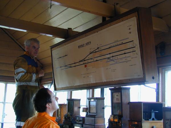
Monday morning sees the box diagram, amnded by David Wittamore, being installed by John Phillips - all signals affected by the changes are by now disconnected.
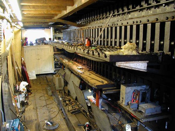
Mid-afternoon on the Wednesday and a pile of completed (and labelled) locking bars has accumulated on the floor of the locking room. The upper locking tray looks almost empty but bottom bars and tappets are complete.
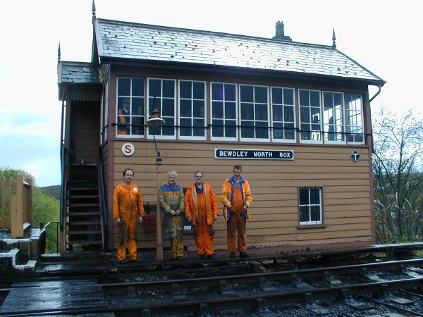
A line up of some of the S&T outside the box on the Wednesday (those absent from this view, Ray Atkins and Tony Neath, were actually doing some work while the photo was being taken).

The electric lock on no. 36 lever has been connected using red stage wiring and a new contact box has been fitted to no. 37 lever in place of the electric lock previously fitted.

The levers have been repainted after the mechanical locking modifications.