 S & T Notes - issue 135
 S & T Notes - issue 135
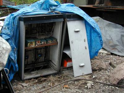
An obituary to location cupboard 2 - struck down in its prime by
the Iron Fairy. No flowers by request.
SIGNALLING NOTES - Chris. Hall
The editor has said that it time to put pen to paper again (well
actually I know that I've got a week or two to produce the article
when the next magazine thuds through the door, so I'll take up the thread
from the last article from the end of August 2000
up to the middle of February 2001.
Christmas has just passed - a month of Santa train running when
we can spend most of the day at the weekend between
Highley and Bridgnorth undisturbed by trains. Except for the Pee-Weigh of course
but they only tend to be around on the Sunday. We can't do much work south of
Highley, as the train service is so frequent, so it's time to do some of the indoor
jobs, which fits in with the usual weather.
Renewals programme
The renewal of location 2 during S&T week in July 2000 was described in the last
article. A works and testing plan was drawn up for the changeover and commissioning in
November 2000 and a team of five (John Phillips, Dave Wittamore, Chris Hall, Steve Curtis and
Dick Lewis) started the work and took possession of the north end of Bridgnorth on
28 November. As soon as the Locomotive Department saw that we had started they
asked to put 813 into the boiler shop siding to be taken away by road.
We allowed 813 through our possession and once the Locomotive Department
realised access to the boiler shop was possible they didn't bother us again.
The existing cable from location 1 (a rather grubby telecomms cable) had to be
disconnected from the old location 2, pulled back and rethreaded through
the new cable duct to the new location 2. However the wound that the cable
had suffered in a tussle with
the CS&TE and an angle grinder (see last issue) became fatal when the cable
(which was under two inches of water at the time) was meggered at an optimistic
1000V. Acceptance
figures of around 20 MOhm are usually quoted but the initial reading was
considerably less than this, then it was noted
that the same reading was obtained with the leads of the megger
shorted together.
A new 'temporary' length of 10 core signalling cable was therefore laid out
to replace the whole of the
damaged cable. This will be fine (until the new troughing can be installed, which we plan
to do in January/February 2001) if
our friends in the Locomotive Department can refrain from covering the cable
in hot ashes.
The old track circuit connections were removed and the cables recovered and scrapped.
This left the wrecked shell of the old location cupboard forlorn and
disconnected. A few minutes later there was no trace of it just some
disturbed earth. This was a poignant moment for the Department - although a few
location cupboards had been renewed twice since the early 1980's, the replacement
of location 2 is the last in the renewal programme which has brought all location
cupboards up to the current standards. The Department therefore celebrated the
occasion in the normal way on the Saturday when the work had been completed.
Commissioning of a new location cupboard involves a lot more work than you may imagine.
Prior to the day when the new location is brought into use and the old location is
decommissioned, a detailed Testing and Commissioning Plan must be produced by the
Tester-in-Charge, who, for the job, was David Wittamore.
The Plan complies with the
format developed by the old B.R. and accepted by Railtrack for the testing and commissioning
of new signalling equipment and systems. This compels the Tester to follow a sequence of
actions to ensure that every single wire, cable and piece of equipment is tested and proved
before it is brought into use. We have been using this rigorous testing and commissioining
process for about the last fifteen years.
An arm repeater for the double disc to be installed at Bewdley North in place
of the existing single disc has to be designed and manufactured and the Departmental
photographer has captured some pictures of the double disc at Bridgnorth
to prove that it can be done (and to assist the design of the necesary fixings)! The
'outside work' at North is proceeding steadily as part of 'phase two' of the
North box work to bring working Distants into use.
Defect rectification
Kidderminster
The circuit controller on the platform 2 motor points (no. 47) was adjusted
and the false lever tail
(bolted on the back of the lever) which drives the circuit controller was
also adjusted which should have (finally) eradicated the problems previously reported.
The acceptance lever has been reported as tight between the reverse and normal check positions
- it was cleaned but remained tight from normal to reverse at the 'B' position and
will need to be stripped down, cleaned and adjusted probably during out-of-traffic
hours. During January and February it was stripped down and cleaned (twice)
and it is now 'as sweet as a nut'. The problem was finally traced to adjustment
of the lock dog which proved critical and required a complete strip down to adjust
it by half a turn.
Bewdley South
A problem was reported that the acceptance lever at Bewdley South could not
be restored after the second driving school returned from Kidderminster on Wednesday of
October half term week although
all track circuit indications were showing clear. Pilotman working was introduced and S&T
attended the following day.
A process of elimination started with the Kidderminster end where all was in order and the
50V feed from Kidderminster to Bewdley was present.
The feed was absent at Bewdley (hence no release to restore the acceptance lever) and thus
indicated a cable
fault. All was in order at the Kidderminster distant but not at the Bewdley South Down Distant (BS0)
and the fault was thus traced to a cable
fault in the 10 core cable between these points. Cores 3 and 4 of the cable were found to have a
direct short but other cores appeared satisfactory.
For most of this distance the cable is buried in the ballast in Bewdley Tunnel so it
didn't look too promising at this stage. However application of Ohms law to
the measured loop resistance gave a rough estimate of the
position of the fault, about 50 yards in rear of BS0. Our Telecoms section
consultant was called upon
on the Saturday afternoon to pinpoint the fault more accurately and used a pulse
echo tester. This
didn't work but before the Signals section had a chance to ridicule these new
fangled devices that didn't work they obtained a more complicated and even newer
fangled device (called a 'cat') that did work
and tied it down to between 20 and 25 yards from the location cupboard.
The cable was cut just beyond this point and a new section of cable to the location
cupboard was jointed and terminated. Examination of the affected cable showed there was
no external evidence of damage.
Subsequently the cable was forensically examined by the Department's expert who
has asked to remain anonymous in this article and the Carr report is eagerly
awaited. About 2' 3¾" from the termination in the location cupboard at the
Down Distant the cores were found to be very compressed, still damp and still
shorted together. As the armouring of the cable was carefully removed the pressure released
and the resistance increased as the cores relaxed. There was no external damage at
the location of the failure. The cable must have been stretched during installation
five years ago where it was threaded around a tight bend through a pipe into the location
and the recent heavy rain had penetrated sufficiently to cause the fault between the two cores.
A fault was reported on 18 November that the up main block was dropping to 'normal'
when the home signal was cleared. On investigation the fault had cleared but a month
later the up main block failed completely. The fuse had blown and the holding coil
had gone open circuit - these faults were repaired on 1 January.
Bewdley North
A track circuit failure was reported on 25 November when 8T was showing occupied when clear (SOWC)
but was also intermittently failing to release the electric locks on levers 8 and 31 whilst
showing clear. This was giving the signalman some difficulty as his instructions
for operating the sealed release (to allow no. 6 points to be unbolted and moved)
state that it will only release the lever when all conditions are correct except that
the track circuit indicates occupied (which it wasn't).
The instructions state "Signalmen are reminded that use of the Sealed Emergency Releases
is permitted only when the lever concerned is locked by reason of the controlling Track
Circuit failing to shew 'clear' when no train or vehicle is standing on the affected
portion of the line. Their use in any other circumstances is irregular and serious
notice will be taken of any misuse. Additionally signalmen are reminded that operation
of the Release Plunger has no effect at all if the controlling Track Circuit indicates
'clear'.".
Normally the track circuit relay (TR) controls a track repeat relay (TPR) which will
either be energised (clear) or not (occupied). In this case the TR is in the signalbox and
there is no need of a TPR. The TR has four sets of contacts (one of which provides
the indication) which may not quite make up at the same time. This appeared to be caused
by very wet track conditions causing the relay to be on the point of deenergising but
could have been caused by a faulty TR (or, as subsequently proved to be the case, by a
faulty insulated rail joint) so it was changed for a serviced spare.
The fault on 31 electric lock persisted and a seperate fault was traced to 8LCC (the lock proving contacts on no.8 electric
lock) which was cleaned and all then appeared in order.
However on 1 January 5T failed SOWC. Investigation showed that the bonding through
the length of the track circuit was in good order but it was noted that the rail to
rail voltage was low (0.12V, normally 0.3V). As an up train approached and occupied 2T, it was noted
that 5TR picked up and this confirmed our suspicion that the IRJ between 2T/5T or
5T/8T was breaking down. The Pee-Weigh were therefore requested to change the IRJ
- this was done on 3 January clearing the fault. The associated track circuits were
tested satisfactorily on 6 January. Electrical faults are always difficult to trace when there's more
than one fault, especially when one of the faults is intermittent.
Highley
The forged bar which holds the detection slide casting a fixed distance from
the stock rail of the yard exit points fractured and was temporarily
repaired. A permanent repair was effected on 17 December which involved forging a square
end onto the relevant fittings so that the length can be made up
using point rodding. The Christmas running provided a good opportunity to
complete this repair.
Bridgnorth
Routine maintenance
The usual, mundane but essential routine maintenance, testing and adjusting equipment
to ensure that it continues to operate reliably, continues in accordance with a
maintenance schedule.
Single Line Worked by Acceptance Lever
The single line between Bewdley South and Kidderminster is worked under Acceptance Lever
Regulations (all the other single lines on the railway are worked under the Electric Train
Token Regulations) and I thought that an S&T perspective of how this operates would
be my 'chosen subject' for explanation in this issue.
The section is track circuited throughout and the Signalman may give
'Train out of Section' for a fully fitted train once the relevant track circuits have
operated in sequence and the single line is clear, often before he can actually see the
train.
In the box each end of the section, an acceptance lever is provided which releases
electrically the section signal lever at the other end of the section. The acceptance
lever is attached to a device called a circuit controller and the acceptance lever can
only be reversed if the single line track circuits between the section signals are clear,
the acceptance lever at the other end of the section is proved normal and if the arm
repeater on the home signal(s) that would be approached by the train is proved in the
Danger position (the occupation key must also be in place 'in position 1' in the release
instrument in South box).
The section signal at the other end of the section may now be cleared, provided that the
single line track circuits remain clear, for a single pull (i.e. once it has been moved
out of the normal position, it will become locked as soon as it is replaced to the normal
position again).
When the section signal lever is pulled then as soon as the arm repeater on the section
signal loses its 'On' indication, the approach locking on that signal will be activated
(approach locking was described in issue 132).
The acceptance lever can be replaced at any time, thus removing the release on the
section signal, as it may be necessary to prevent the approach of a train in an emergency,
but there is an electric lock which will stop it short of the normal position (just
short of the normal position so that no mechanical locking is released). This lock
will always be free in normal circumstances but will be locked unless the single line
track circuits are free, the occupation key is in its correct place and the section
signal at the other end of the section is free of approach locking (F.O.A.L.). This
means that the signal arm is proved at Danger and the approach locking has been
released.
The only mechanical locking provided on the acceptance lever is that it is locked
normal unless the section signal lever is normal. Conversely the section signal
lever is locked normal unless the acceptance lever is normal. The Driver's authority
to enter the section is therefore given by clearance of the section signal proving that
the section is empty and that no train has been given permission to approach from the
opposite direction.
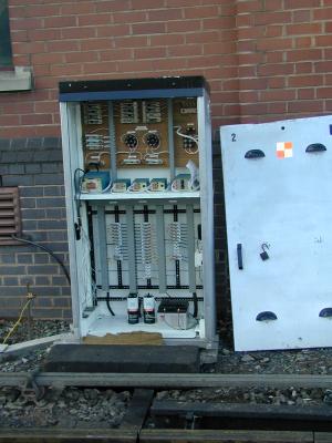
The new location 2 at completion of commissioning.