 SVR S&T Dept.

SIGNALLING NOTES - Chris. Hall
As I mentioned in the last article, we had started dismantling our point rodding at the south end of Bridgnorth and by the end of January had removed all of our equipment Éon the surfaceĹ between the two platform lines and around the yard crossover south of the footbridge. We had decided to leave the concrete bases in situ, taking a calculated risk that some might be damaged during the P-Way work and have to be dug out and reinstated rather than having to dig out and reinstall all of them.
After digging out most of the old ballast, new ballast was laid and a fibre carpet placed on the surface. I remember thinking that I hoped our concretes would not be Éout of sight, out of mindĹ but in the event only two concretes and a cast plate were casualties.
The first set of points to be laid (no. 12 points) were being built from a kit of parts whilst we removed our equipment from around the yard points (no. 14 crossover). These points had been laid out on flat ground at works and the stretchers cut to size but these had to be replaced and re-cut when rebuilt on site clear of the road bridge. There would not be enough room between the sleepers and the bridge beams for concrete bases by the side of the track and so in early planning we had specified extended sleepers onto which we could attach our drive cranks.
Unfortunately standard extended sleepers would foul the bridge beams and were not fitted. Good communication between S&T and P-Way meant that revised plans for extended sleepers, cut to fit around the bridge beams, could be agreed and sleepers exchanged after the points had been laid and before the yard points had been delivered.
Fitting the cranks to drive 12 points and the associated FPL (no.11) and reinstating the rodding run was relatively straightforward although we had to swap the positions of the rods for 11 and 12 south of the kipping coaches to line up. Time was on our side here: we could get on with this while the yard crossover was being laid. Dan had refurbished an electrical detection box and a longer cable was run to connect this up. At this stage we could connect the re-positioned compensator to the box but the points would have to remain disconnected until work on the yard points was complete.
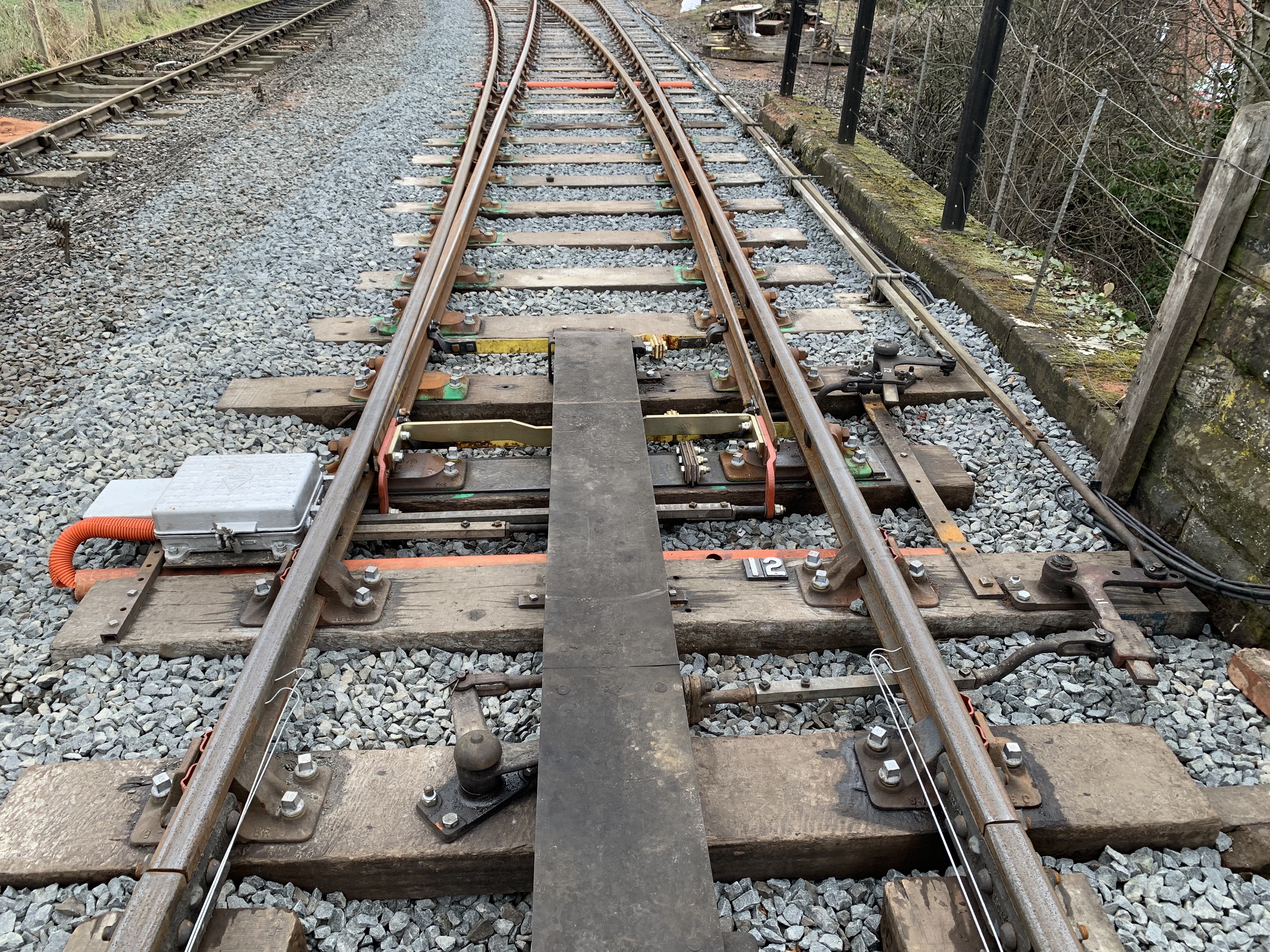 No.12 points were fairly complete by 16th March, although not yet connected to the signal box. Below: on the same day, work on 14B points was still only just starting. [Photo: Matt Morgan]
Plan ÉAĹ was that the yard crossover would be replaced on a Élike for likeĹ basis in the same position as before. This would allow simple reconnection, putting everything back where it was, all carefully marked when it was removed as it would all be the same length, using existing concrete bases left in position. Unfortunately the existing trackwork in the yard was quite worn and the rail height of the new rail on the crossover was 8mm taller. Not replacing the first set of points at the same time had therefore proved to be a false economy. A short length of rail had to be cut so that a standard insulated joint could be used with a stepped fishplate joint to the old rail. This meant that the ÉBĹ end of the crossover had to move two feet further away from the box. Our workload more than doubled but the available time had reduced as the points had been delivered later than planned.
The broken concretes and plate were replaced from stock. Attempting to lift a compensator by the road railer to get it to the correct height using the concrete bases as lifting points did not work and we had to replace another two bases and do it the hard way by digging out. With the points in a different position we embarked on the rather long-winded job of digging out concrete bases for detection and drive rods and replanting them in a new position. The disc signal reading out of the headshunt would also have to be moved as the fouling point between the headshunt and the points had changed.
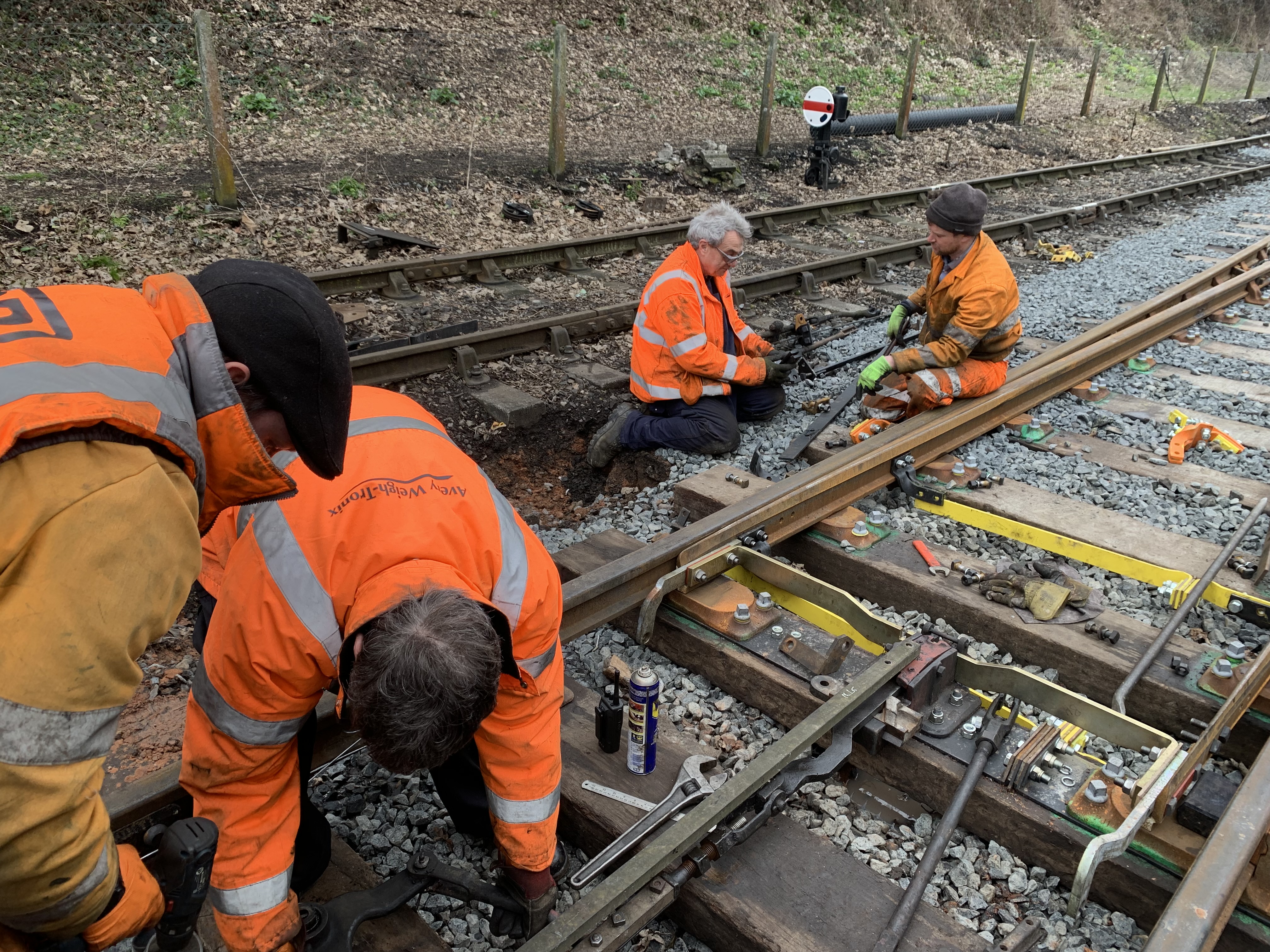 Above and Below: On 16th March, work on 14B points was still only just starting.
The yard crossover had friction in all the wrong places, the sleeper under the soleplate was ÉsquishyĹ, switch rails were not supported by some of the chairs, the switches would not close up and the stocks rails moved around. Nothing unusual here so Hagley Hall was driven backwards and forwards over the pointwork to help stabilise it. We had to go back four times to tighten the bolts on the FPL casting and will have to return and fit a plate underneath the sleeper. Tolerances here are tight and regularly checked. The concrete bases for the compensator under the footbridge for 14 points were sat on a large pipe thought to be supplying the water column and the compensator was moving - more work is needed here.
Sleeper positions had changed so the FPL covers were now the wrong length and a replacement would need to be brought from Kidderminster after services resume. Much assistance was provided by Engineering Services Motive Power (Bridgnorth Loco) when metal had to be heated and bent and the P-Way were able to assist with use of their battery powered large grinder (we must get one of these) and rail broach (detection floats on its base but is stood off from the rail by a piece of rodding bolted to the rail). The FPL stretcher comes with narrow slots which can be precisely cut to the right width and depth with a hacksaw on site using these as a guide.
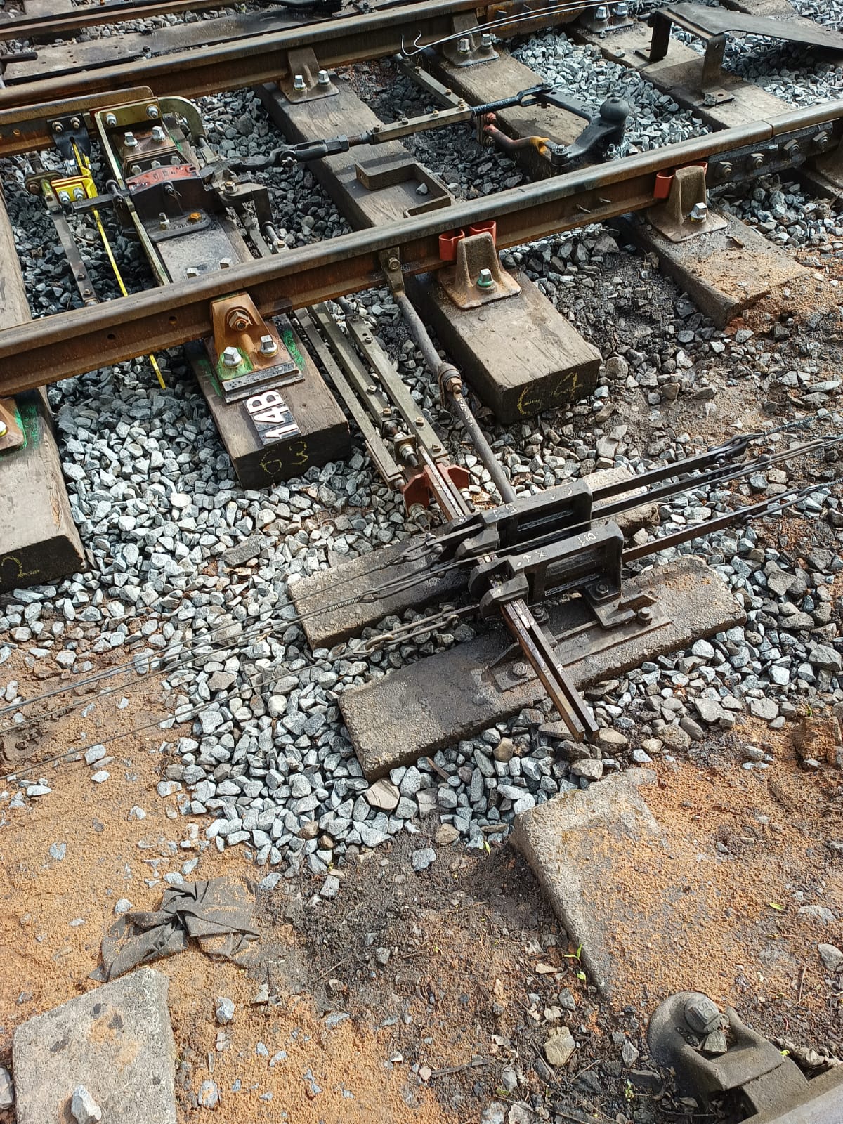 It is 30th March and services will resume very shortly. 14B points are complete and the whole installation has been adjusted, tested and commissioned today. Photo: J.Smith
Throughout the work the line was under possession, with extra work sites as necessary with the S&T providing the ÉPerson in ChargeĹ (PICOP), and this was handed back after completion of commissioning on 30th March. It is noteworthy that S&T volunteers made this work possible, some coming in two or three days a week for the duration and pretty much every member of the Department contributed something to the project.
 By 13th April the new trackwork has settled down nicely, with only a little lifting and packing still to do. [Photo: John Smith]
Other work had been identified for the close season to replace some worn cranks at Bewdley South but we were too busy at Bridgnorth to do this before the service resumed. We had brought three compensators and an adjustable crank from our stores: these were items we had refurbished by re-bushing worn holes and put into stock until required. Two of these were for 15 FPL (Up Main/Back Road) and we realised that the bottle adjuster was seized and had probably not been used for fifty years. After some repairs to my car on Easter Sunday, by which time the first two Down trains had gone, we took a disconnection on 15 FPL to take the bottle to the workshop and apply heat, with the assistance of 1501 group (our gas bottles having been sacrificed for economy reasons), and brute force (we are good at that) to free it up. Stopping short of destroying it we managed to bend it back into approximate shape and refit it a few minutes before the next Down train.
Disconnecting 13 points (main crossover) between passenger trains we were able to replace two compensators without causing any delay with the cooperation of the signalman and his trainee. Several adjustments were required before we were both happy that the points felt right but we noticed that a crank on the lead off was worn and would need to be replaced - we will be able to make a temporary repair but a permanent repair would be a close season job.
The following Sunday had a more intensive train service and we were able to take the train to Kidderminster to find a replacement bottle adjuster for 15 FPL. At a convenient point in the timetable, between trains, we were able to disconnect 15 FPL again and replace the bottle adjuster, the adjustable crank and the compensator. As with a lot of our work, when we had finished it all looked the same as when we started but worn equipment had been refurbished. The recovered items will be refurbished and put back into stock.
The signalman at Bewdley North had complained that 28 signal lever (Down Starter) was too hard to pull and it transpired that routine maintenance had caused the locking bar between levers 2 and 28 (which had been altered in 2002 when No. 4 lever was shuffled to No.19 position to allow lever 1 to operate the Up Distant) to become tight. We may need to machine a new piece of locking to resolve this fully.
 The offending piece of locking, bar 1 in channel A with the top bars removed for clarity.
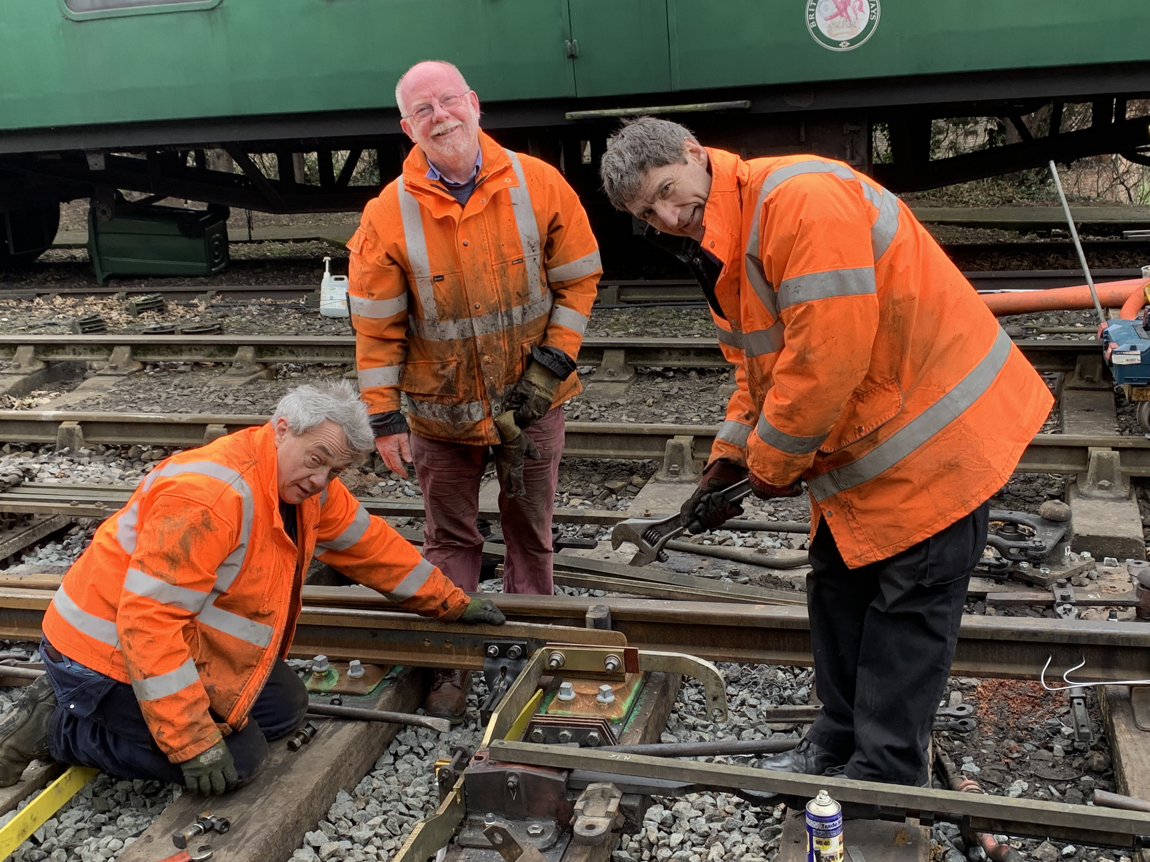
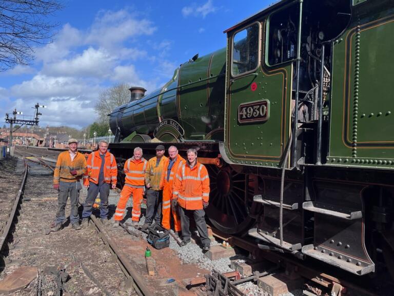 Hagley Hall was driven back and forth to stabilise the pointwork, after which the team pose for a photo. [Photos: Matt Morgan]
A reminder that this article, as well as other information on Signal Engineering, can be viewed in full colour here on the unofficial Signal Engineering web site.